


SK-91F467-FLEXRAY V1.1
Jumpers and Switches
© Fujitsu Microelectronics Europe GmbH - 31 - FMEMCU-UG-910017-11
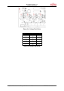
3.7 CAN0 – CAN2
Three high-speed CAN-transceivers (PCA82C250) are on-board to connect all available on-
chip CAN to 9-pin D-Sub connectors (X9, X10 and X11).
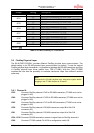
JP82 Connects MCU RX0 to CAN transceiver U15
JP83 Connects MCU TX0 to CAN transceiver U15
JP87 Connects MCU RX1 to CAN transceiver U18
JP88 Connects MCU TX1 to CAN transceiver U18
JP89 Connects MCU RX2 to CAN transceiver U19
JP90 Connects MCU TX2 to CAN transceiver U19
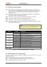
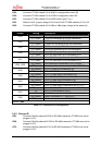
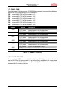
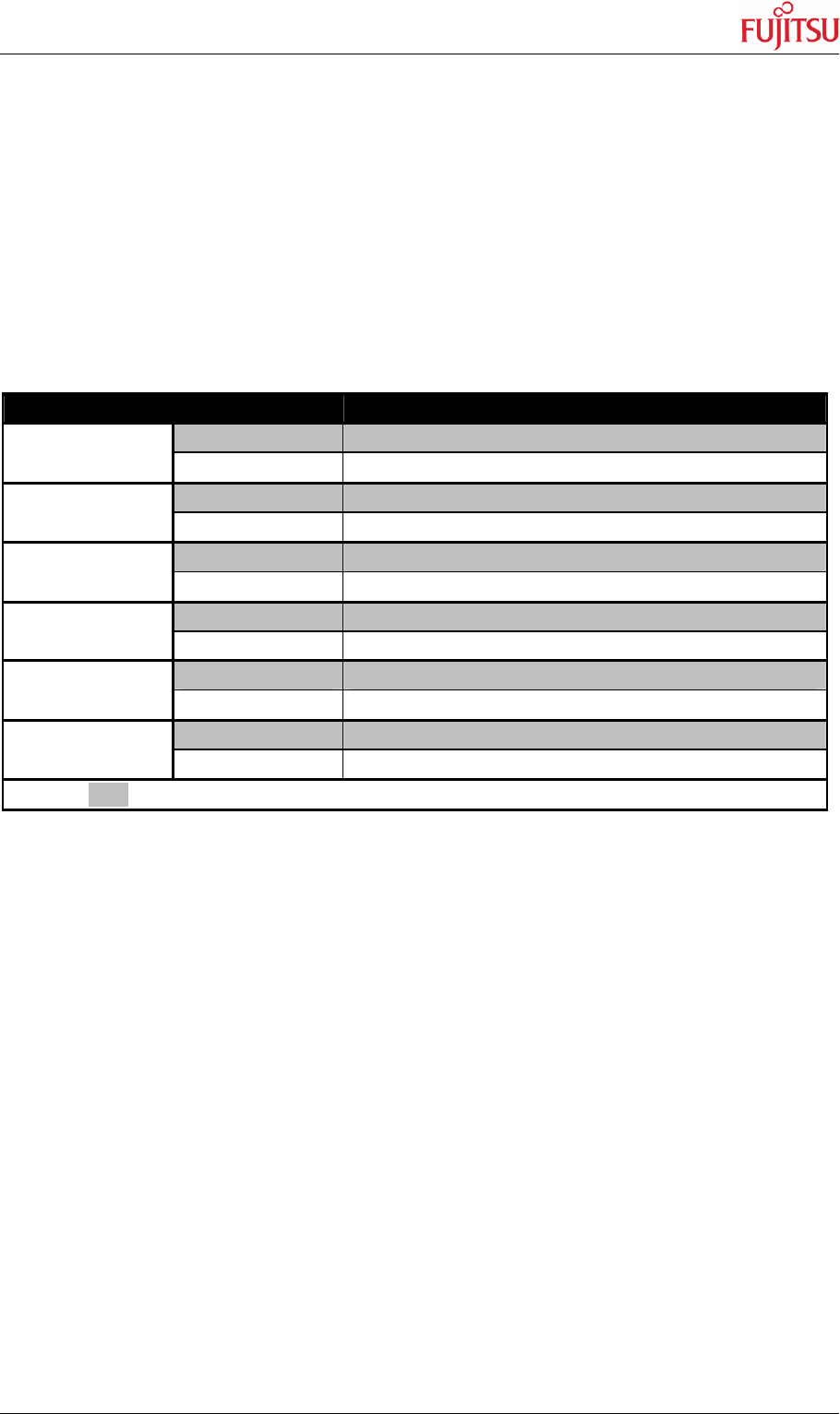
Jumper Setting Description
ON (closed) CAN0 RxD connected to MCU
JP82
OFF (open) No connection to the microcontroller
ON (closed) CAN0 TxD connected to MCU
JP83
OFF (open) No connection to the microcontroller
ON (closed) CAN1 RxD connected to MCU
JP87
OFF (open) No connection to the microcontroller
ON (closed) CAN1 TxD connected to MCU
JP88
OFF (open) No connection to the microcontroller
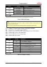
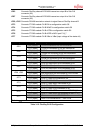
ON (closed) CAN2 RxD connected to MCU
JP89
OFF (open) No connection to the microcontroller
ON (closed) CAN2 TxD connected to MCU
JP90
OFF (open) No connection to the microcontroller
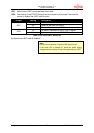
Default: grey
Table 3-15: CAN-MCU connection
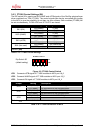
3.8 LIN / RS-232 UART
There are three UART connectors X1, X4 and X8 (9-pin D-Sub) on-board, which can be
used for RS-232 or LIN communication (to get information in detail about pin usage, please
refer to chapter 4.2 UART / LIN Connector (X1, X4, X8)). The LIN transceiver needs to be
configured as LIN-master or LIN-slave.