


SK-91F467-FLEXRAY V1.1
Appendix
FMEMCU-UG-910017-11 - 72 - © Fujitsu Microelectronics Europe GmbH
10.4 Figures
Figure 2-1: AC plug adapter................................................................................................. 12
Figure 2-2: AC plug adapter selection .................................................................................. 12
Figure 2-3: DC voltage selection .......................................................................................... 12
Figure 2-4: Low voltage adapter selection............................................................................ 12
Figure 2-5: Starter kit status after power on ......................................................................... 13
Figure 2-6: Default Jumper Settings..................................................................................... 16
Figure 2-7: Softune Workbench start menu location............................................................. 17
Figure 2-8: Softune Workbench V6 IDE ............................................................................... 18
Figure 3-1: MCU Mode Switch ............................................................................................. 19
Figure 3-2: FlexRay CC Mode Switch .................................................................................. 20
Figure 3-3: FlexRay CC SPI-Mode Switch ........................................................................... 21
Figure 3-4: Voltage Test Points............................................................................................ 23
Figure 3-5: FT1080 Control Switch....................................................................................... 30
Figure 4-1 Power Connector ................................................................................................ 38
Figure 4-2 UART Connector................................................................................................. 38
Figure 4-3: CAN Connector.................................................................................................. 39
Figure 4-4: FlexRay Connector ............................................................................................ 39
Figure 4-5: FlexRay Physical Layer Connector .................................................................... 40
Figure 4-6: User LEDs / LCD ............................................................................................... 41
Figure 4-7: In Circuit Programming Connector ..................................................................... 42
Figure 4-8: Layout of DIN VG Connectors............................................................................ 44
Figure 5-1: Softune Workbench main window ...................................................................... 45
Figure 5-2: Open Softune Workbench workspace (*.wsp) .................................................... 48
Figure 5-3: Project configuration selection ........................................................................... 49
Figure 5-4: Open Softune Workbench Linker mapping file ................................................... 50
Figure 5-5: Softune Workbench Linker Mapping .................................................................. 50
Figure 5-6: Start Softune Workbench Monitor Debugger...................................................... 51
Figure 5-7: MB91F467D and mode pin DIP switch............................................................... 53
Figure 5-8: Reset button and user LED................................................................................ 53
Figure 5-9: SWB debugging window .................................................................................... 54
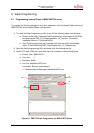
Figure 6-1: FME FR-Flash Programmer for MB91F467D series........................................... 61
Figure 6-2: FME Flash Programmer output message window.............................................. 63
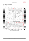
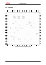
Figure 8-1: Board Layout (Top Side).................................................................................... 65
Figure 8-2: Board Layout (Bottom Side)............................................................................... 66