


SK-91F467-FLEXRAY V1.1
Connectors
© Fujitsu Microelectronics Europe GmbH - 39 - FMEMCU-UG-910017-11
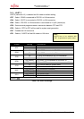
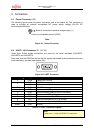
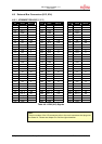
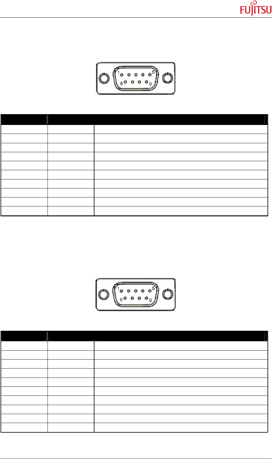
4.3 CAN Connector (X9, X10, X11)
Three 9-pin D-Sub male connectors are used for the CAN interfaces CAN0, CAN1 and
CAN2.
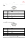
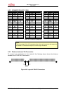
Figure 4-3: CAN Connector
Pin Number Pin Signal Description
1 NC Not used
2 CANL LOW-level CAN voltage input/output
3 GND Ground
4 NC Not used
5 NC Not used
6 NC Not used
7 CANH HIGH-level CAN voltage input/output
8 NC Not used
9 NC Not used
Shield GND Ground
Table 4-2: CAN Connector Signals
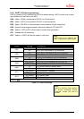
4.4 FlexRay Connector (X2, X6)
Two 9-pin D-Sub male connectors are used for the two FlexRay channels A and B. As
default RS-485 is used at SK-91F467-FLEXRAY.
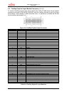
Figure 4-4: FlexRay Connector
Pin Number Pin Signal Description
1 NC Not used
2 BM Bus line Minus
3 GND Ground
4 NC Not used
5 User Connected to optional pin head (CH-A: J9; CH-B: J14)
6 NC Not used
7 BP Bus line Plus
8 NC Not used
9 NC Not used
Shield Shield Connected to shield of FT1080 modules
Table 4-3: FlexRay Connector Signals