1.2 Configuration of Optical Disk Drive
C156-E227-01EN 1-7
1.2.2 Configuration
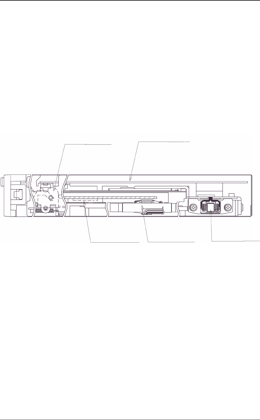
Figure 1.3 shows the configuration of the optical disk drive.
The optical disk drive consists of a mechanical section, a fixed optics section, a
control circuit section, and an actuator.
The mechanical section includes the spindle motor, actuator section, bias magnet,
and cartridge holder vertical motion mechanism.
The fixed optics section consists of the optical components, position detector, and
LD controller.
The control circuit section includes the drive control circuit section and I/F circuit
section.
Mechanical section
Control circuit section
Spindle motor Actuator
Fixed optics section
Figure 1.3 Configuration of optical disk drive
1.2.3 Mechanical section
(1) Loading and ejecting an optical disk cartridge
The optical disk drive includes a cartridge load mechanism and an auto eject
mechanism. If an optical disk cartridge is manually inserted in the drive's slot as
far as it will go, the cartridge load mechanism automatically lowers the cartridge
and mounts it on the spindle motor. If the Eject button on the front panel is
pressed, the auto eject mechanism automatically ejects the cartridge.
(2) Spindle motor
An optical disk cartridge hub and the spindle motor shaft are magnetically
combined. Therefore, a disk rotates as fast as the spindle motor shaft rotates. The
spindle motor, a DC brushless motor, provides high-speed rotation at 5,455 rpm
and 3,637 rpm and high-accuracy rotation at ± 0.1%.


