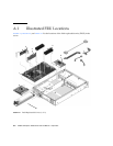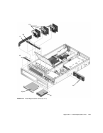
A-4 SPARC Enterprise T2000 Server Service Manual • April 2007
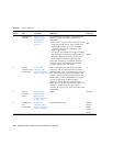
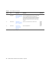
TABLE A-1 Server FRU List
Item No. FRU
Replacement
Instructions Description FRU Name
*
1 Motherboard
assembly
Section 5.2.7,
“Removing the
Motherboard
Assembly” on
page 5-19
The motherboard assembly is comprised of the
following boards that must be replaced as a
single FRU:
• CPU board – Comprises the central processing
subsystem for the server, which includes the
UltraSPARC T1 CPU processor, 16 DIMM
connectors, the memory controllers, and
supporting circuitry.
• I/O board – Provides the I/O logic, including
the connectors for the PCI-X and PCI-Express
interfaces, Ethernet interfaces, all the power
interconnections, and miscellaneous logic.
Note: This assembly is provided in different
configurations to accommodate the different
processor models (4, 6, and 8 core).
MB
IOBD
2 System
controller card
(OSP board)
Section 5.2.5,
“Removing the
System Controller
Card” on page 5-17
This board implements the system controller
subsystem. The SC board contains a PowerPC
Extended Core, and a communications processor
that controls the host power and monitors host
system events (power and environmental). The
board holds a socketed EEPROM for storing the
system configuration, all Ethernet MAC
addresses, and the host ID. This board only
draws power from the 3.3V standby supply rail,
which is available whenever the system is
receiving AC input power, even when the system
is turned off.
SC
3 System
controller
battery
Section 5.2.21,
“Removing the
Battery on the
System Controller”
on page 5-40
Battery. SC/BAT
4 PCI-Express
and
PCI-X cards
Section 5.2.1,
“Removing PCI-
Express and PCI-X
Cards” on page 5-9
Optional add-on cards. PCIE0
PCIE1
PCIE2
PCIX0
PCIX1


