


XG2600 Hardware Guide Chapter 1 Getting Started
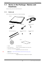
Items in the Package / Names and Functions
20
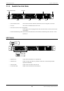
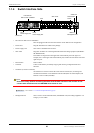
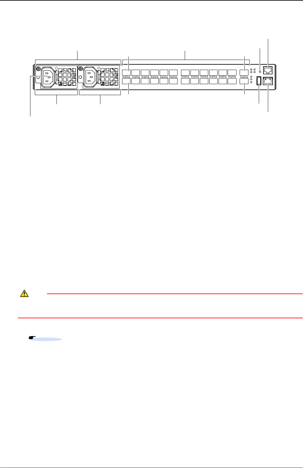
1.1.4 Switch Interface Side
• PSU Slots for Rear-Access Installation
PSUs are plugged in the slots when the switch is used in Rear-Access configuration.
• Power Inlet Plug the attached Power Cable in the package.
• Power Supply Unit This switch is installed with two PSUs.
• SFP+ Slots Plug SFP+ modules for connecting Ethernet based networking equipment (10GBASE-
SR/10GBASE-LR).
Port number is assigned from the upper side of the leftmost port to the right. For
example, Port 1 is the upper side of the leftmost port, and Port 26 is the lower side of the
right most port.
• Reset Switch Push to reboot.
• USB Port Connect USB memory for backup-copying and restoring configuration files and
firmware.
• Serial Port (Console Connection)
The Serial Port is used to connect the switch with the console (PC) for setting and
command line interface via the attached Console Cable (RJ45 to Serial Adapter) and
RS232C crossover cable (D-SUB9) .
Caution
Serial Port is only used for connecting the switch with RS-232C interface of the console. Do not
connect other interfaces such as LAN/ISDN which cause an error.
• Management Port This is used to connect Ethernet based (10/100BASE-TX) networking equipment. Use
Category-5 LAN cables.
Reference
User’s Guide "1.1.5 Console Port Specifications" (pg.28)
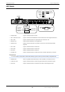
SFP+Slots
SerialPort
PSU1
PowerSupplyUnit
PowerInlet
ManagementPort
USBPort
ResetSwitch
PSUSlotsfor
Rear-AccessInstallation
PSU2
PowerSupplyUnit
Port1
Port2 Port26
Port25