


XG2600 Hardware Guide Chapter 2 Installation
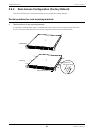
Installation of the switch
32
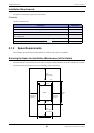
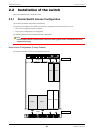
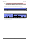
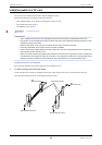
The diagram below shows in which slots PSUs need to be installed and airflow direction of the fans.
: Installing – : not installing
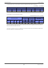
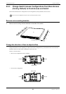
The LED lights in a correct configuration as follows:
– : Unsupported because the unit is not installed
If the LED indicators are different from the above, it may be due to the incorrect configuration of PSUs and/or Fans, or
there may be failures with PSUs and/or Fans.
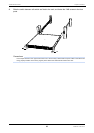
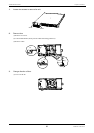
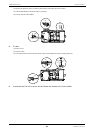
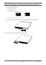
If the switch is installed in Front-Access configuration, it is necessary to remove PSUs and install them in different slots
than factory default ones, and change direction of fans.
Power Supply Unit Fan Unit
Switch Interface Side Switch Fan Unit Side FAN1 Slot FAN2 Slot
PSU1 Slot PSU2 Slot PSU1 Slot PSU2 Slot Installation Airflow Installation Airflow
––
Exhaust
Exhaust
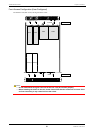
Switch Interface Side
Power Supply Unit Switch Fan Unit Side
Switch Interface
Side
Switch
Fan Unit Side
Slot 1/Slot 2
READY CHECK PSU1 PSU2 FAN
PSU1 PSU2 PSU1 PSU2
STATUS OUTFLOW
POWER
Green Off Green Green Green – – Green Green Green Green