


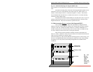

Magnum 6K32 & 6K32T Managed Switch Installation and User Guide (12/05)
24
www GarrettCom com
..
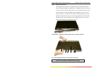
3.2.2 Connecting Fiber Optic SC-type
, "Snap-In"
The following procedure applies to installations using a PM with SC-type fiber
connectors, i.e., using 6K-MSC or 6K-SSC (single mode) etc.
When connecting fiber media to SC connectors, simply snap the two square male
connectors into the SC female jacks of the 6KPM until they click and are secure.
3.2.3 Connecting Single-Mode Fiber Optic
When using single-mode fiber cable, be sure to use single-mode fiber port
connectors. Single-mode fiber cable has a smaller diameter than multi-mode fiber cable
(9/125 microns for single-mode, 50/125 or 62.5/125 microns for multi-mode where xx/xx
are the diameters of the core and the core plus the cladding respectively). Single-mode
fiber allows full bandwidth at longer distances, and may be used to connect 10 Mb nodes
up to 10 Km apart, or 18Km with the 6K-SSC.
The same procedure for multi-mode fiber applies to single-mode fiber
connectors. Follow the steps listed in Section 3.2.2 above.
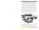
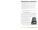
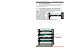
3.2.4 Connecting Twisted Pair (RJ-45,CAT3, CAT5, Unshielded or Shielded)
The RJ-45 ports of the Magnum 6K32T can be connected to the following two
media types: 100BASE-TX and 10BASE-T. CAT 5 cables should be used when making
100BASE-TX connections. When the ports are used as 10BASE-T ports, CAT 3 may be
used. In either case, the maximum distance for unshielded twisted pair cabling is 100
meters (328 ft).
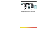
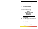
Media
IEEE Standard Connector
Twisted Pair (CAT 3, 4, 5) 10BASE-T RJ-45
Twisted Pair (CAT 5) 100BASE-TX RJ-45
NOTE : It is recommended that high quality CAT. 5 cables (which work for both 10 Mb
and 100Mb) be used whenever possible in order to provide flexibility in a
mixed-speed network, since dual-speed ports are auto-sensing for either 10 and
100Mb/s.
The following procedure describes how to connect a 10BASE-T or 100BASE-
TX twisted pair segment to the RJ-45 port. The procedure is the same for both
unshielded and shielded twisted pair cables.
1. Using standard twisted pair media, insert either end of the cable with an RJ-45
plug into the RJ-45 connector of the port. Note that, even though the connector is
shielded, either unshielded or shielded cables and wiring may be used.
2. Connect the other end of the cable to the corresponding device
3. Use the LINK LED to ensure proper connectivity by noting that the LED
will be illuminated when the unit is powered and proper connection is
established