


Magnum 6K32 & 6K32T Managed Switch Installation and User Guide (12/05)
33
www GarrettCom com
..
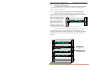
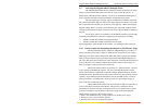
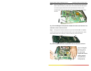
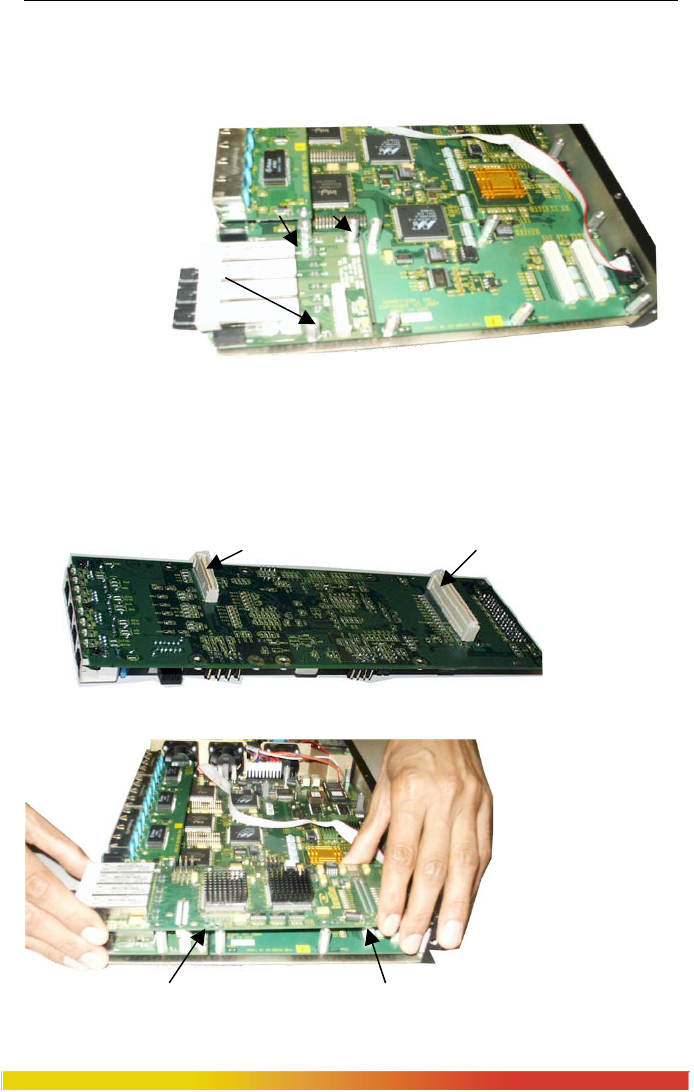
Step 2. Placed Granddaughter board (as shown in fig. 3.5.2a and 3.5.2b) on the chassis
built in stand off (female) provided at the front of the 6K32T Main Board and
screw down tightly with the three 5/16 stand-off (male) on the top of the
Granddaughter board The 5/16 stand off has been used to place the daughter
board on the top of the granddaughter board and latch it securely.
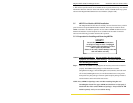
Fig 3.5.2b Granddaughter Board placed in modular slot and secured with three 7/16
stand-off’s as shown with arrow mark
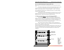
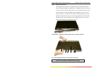
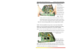
Step 3. The figure here illustrates the basic layout of an individual PM card. 6KPM
card fits into the space provided on the main board over the grand-daughter Bd. and the
male latched cream color connector( as shown in above fig. with arrow mark).
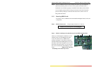
Fig 3.5.2d: Daughter Board shown upside down with two male latch connectors
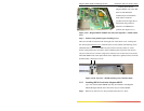
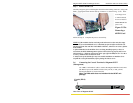
Fig 3.5.2e Daughter
Bd. Being placed
over the Grand
daughter Bd. and the
mating connector
being matched to
lockup properly