


Magnum 6K32 & 6K32T Managed Switch Installation and User Guide (12/05)
57
www GarrettCom com
..
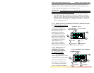
The manual power “On-Off” Switch (optional) is used for powering the unit on
and off when it is placed into or taken out of service.
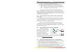
B3.0 APPLICATIONS FOR DC POWERED SWITCHES
Magnum 6K32T Fiber Switches are easily installed in a variety of applications
where -48VDC, 24VDC and 125VDC power is used as the primary power source. The-
48VDC, 24VDC and 125VDC power configuration provides an Ethernet networking
solution utilizing a special power supply in a Managed Switch.
The –48VDC solution is particularly useful in the telecommunication industry,
where it is common for facilities to operate on -48VDC power. Such companies include
regular and wireless telephone service providers, Internet Service Providers (ISPs) and
other communication companies. In addition, many high availability equipment services,
such as broadcasters, publishers, newspaper operations, brokerage firms and other
facilities often use a battery backup system to maintain operations in the event of a power
failure. It is also frequently used for computer system backup, management and
operations monitoring equipment.
The 24VDC and 125VDC solution are particularly useful in the Industrial
environment, where it is common facilities to operate on 24VDC or 125VDC power. The
125VDC solution is mainly used in power utilities, such as electrical substations,
electrical generating plants, etc. The 24VDC applications are mainly in the Industrial
environment, such as factory floor, HVAC equipment, military equipment, etc.
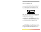
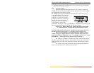
B4.0 INSTALLATION
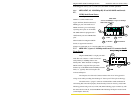
This section describes the installation of the -48 VDC, 24VDC and 125VDC
power source leads to the -48 VDC, 24VDC and 125VDC power terminal block on the
Magnum 6K32T’s. (see figure at right).
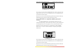
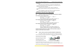
In this picture, the -48VDC terminal block on the Magnum 6K32T is located
on the rear of the unit and is equipped with three (3) screw-down lead posts. It is similar
for 24VDC and 125VDC options on Magnum 6K32T. The leads are identified as
negative (-),
positive (+), and chassis ground (GND).
Figure B4.0: -48VDC Terminal Block on Magnum 6K32T-48VDC
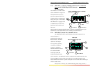
The actual connection procedure is very straightforward. Simply connect the
leads to the Magnum unit, beginning with ground. Ensure that each lead is securely
tightened.
Note: The GND should be hooked up first. The 6K32T unit has a floating ground, so
the user may elect to Ground either + or = terminal to suit the customer’s use.
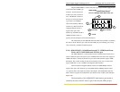
Before connecting hot lines to the Terminal Block of –48VDC, 24VDC or
125VDC, always use a digital voltmeter to measure the output voltage of the power
supply and determine the lead which is more “+ve potential”. The more “+ve” voltage