


Magnum 6K32 & 6K32T Managed Switch Installation and User Guide (12/05)
35
www GarrettCom com
..
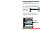
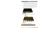
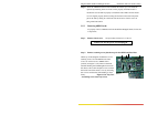
Step 8. Once the 6KPM cards have been installed, the chassis top cover should be
replaced by matching at the two front corners properly and slide in until it
reaches the rear end and fit properly to match the holes. Make sure the chassis
cover is aligned properly before securing the enclosure. Place the front panel
part at the end by sliding in to the front side and secure it with 12 screws as
being mentioned earlier.
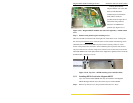
3.5.3 Removing 6KPM Cards
To properly remove a 6KPM card from the 6K32T Managed Switch, follow the
3 steps below.
Step 1. Remove chassis cover See procedures in Section 3.5.1 above.
Caution: Be sure the power cord is unplugged.
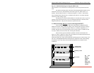
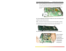
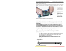
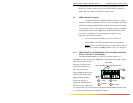
Step 2. Remove retaining screws placed on top for the 6KPM and Face Plate
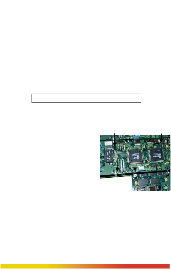
On the top of the daughter module there are six
retaining screws for each 6KPM card. These
screws are used to secure a 6KPM card in
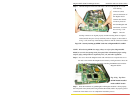
position (see Figure 3.5.3a). Remove the three
standoffs holding the Granddaughter board with
the chassis. The screen faceplate screws out from
the inside front of the chassis cover by loosening
the 4 screws and bracket while holding it down
firmly. Figure 3.5.3a: Top View
- 6 retaining screws shown by arrows