


Magnum 6K32 & 6K32T Managed Switch Installation and User Guide (12/05)
34
www GarrettCom com
..
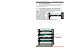
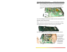
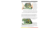
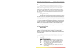
Step 4. Hold the daughter board with both hands at the end and align the two cream
color latching
connectors (male)
placed at the bottom of
the daughter board
with the other female
connector placed on
the Granddaughter and
main board. As shown
above in Fig. 3.5.2e
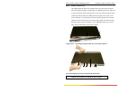
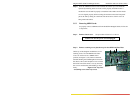
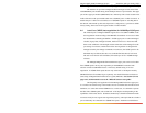
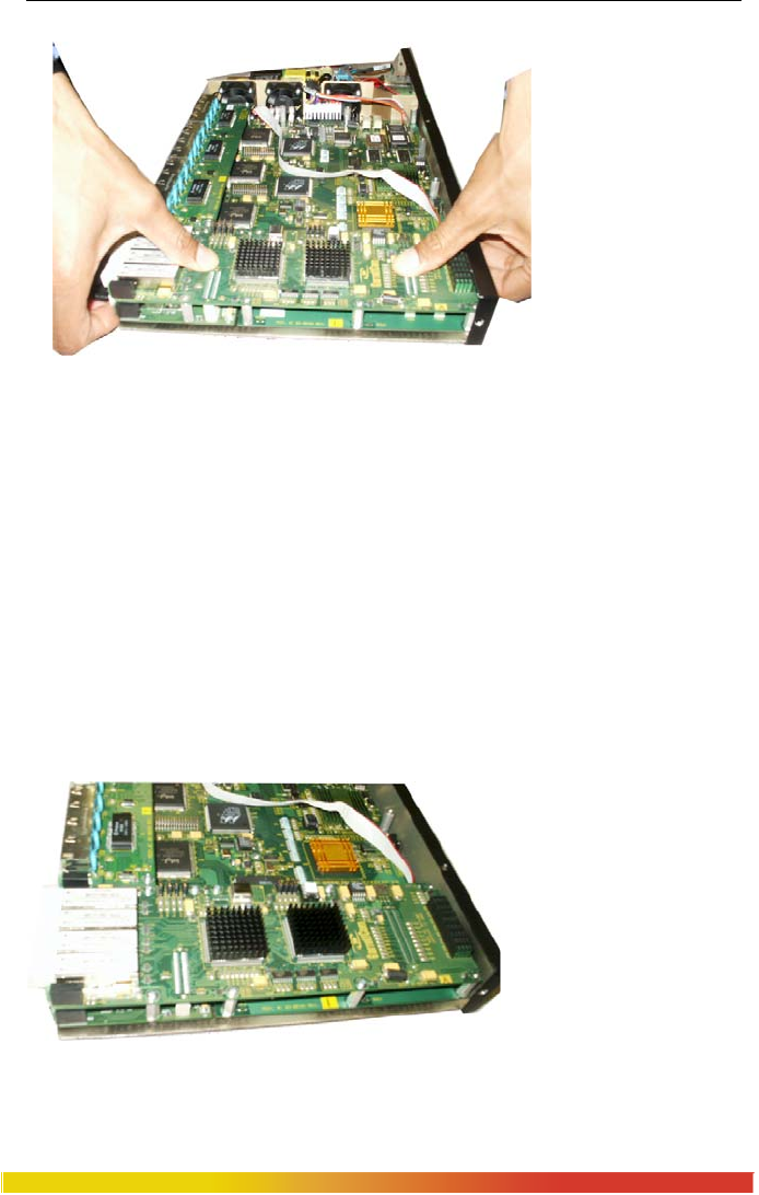
Step 5. Once the
latching connectors are aligned properly and the mounting holes are aligned
with stand offs then press slowly and firmly with two fingers (as shown below
in Fig. 3.5.2f) on the top of the latching connectors until the connectors latched
Fig.3.5.2f: Securely latching up 6KPM Cards into a Magnum 6K32T & 6K32
NOTE:. When leaving 6KPM slots empty, always use a face plate (Magnum 6K8-
BLNK) to cover the slot opening in the front panel. This will maintain proper cooling
air flow, safety, and operation as required by FCC, CE, and other regulations.
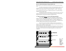
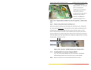
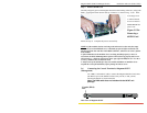
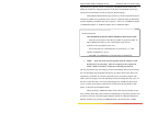
Step 6. Now screw down the daughter board with 7 #440 screws except the last two at
the end, so that it holds the daughter board securely. The figure below shows the
top view of 6KPM card after successfully installing the 6KPM cards inside the
Magnum 6K32T.
Fig. 3.5.2g Top View :
6KPM Module installed
inside a 6K32T Switch
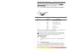
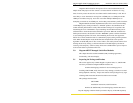
Step 7. Once the installation of granddaughter and daughter modules is done properly,
the front panel screen plates(come along with the 6K-module) need to be properly placed
on the front of the chassis cover to complete the installation process.