


12
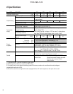
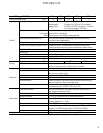
FVR-C9S-7UX
Mounting plate: Heat sink temperature will
reach +90°C during operation. Please use
thermostable material for drive mounting
plate.
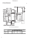
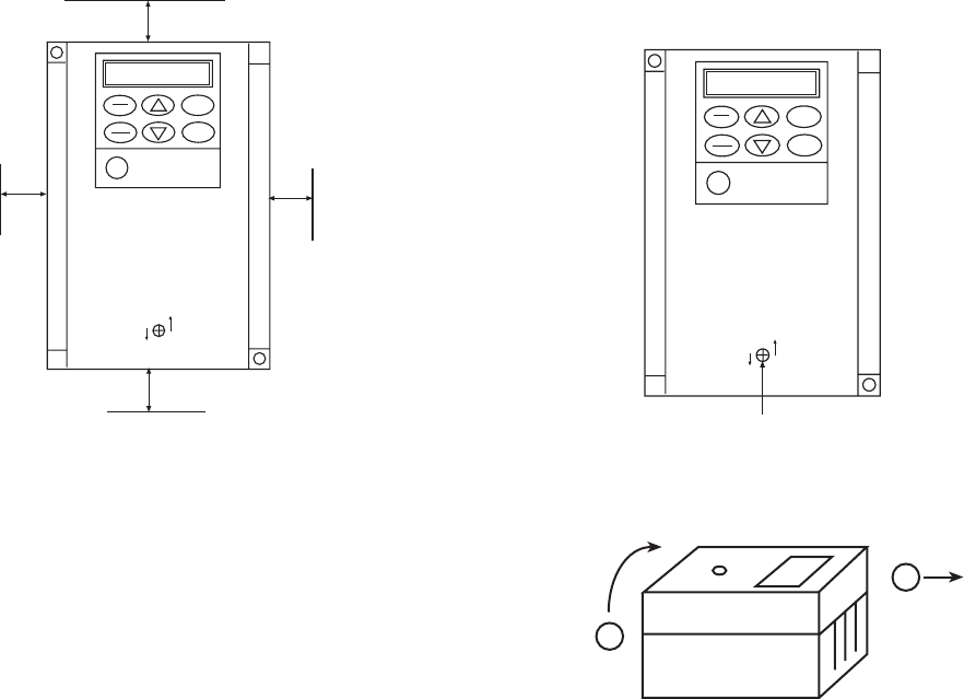
Multi-mounting: When 2 or more drives are
installed within the drive switchboard, ar-
range them side by side, keeping space
(shown in the above figure) between each
drive. If the drives must be lined up vertically,
provide adequate ventilation so that the hot
air from each drive will not affect the one
above it.
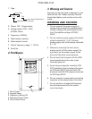
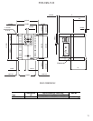
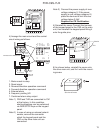
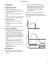
7. Wiring
Perform wiring in accordance with the fol-
lowing procedure:
1) Remove the cover mounting screw at the
center of the cover.
2) Hold the lower end of the cover, lift it up
and remove the cover
3) Remove the keypad panel from the main
unit, and disconnect the harness from the
CN2 at the same time.
6. Installation Instructions
Installation Conditions
Install the drive in a location which meets the
following requirements:
• The ambient temperature should be be-
tween -10°C and +50°C.
• Install the drive in the environment of
pollution degree 2. If environment is pollu-
tion degree 3 or 4, the drive should be
installed in a cabinet of IP54.
• Install the drive in the atmospheric pres-
sure of 900mbar or more.
• Install the drive in the vibration of 232
inches/s
2
(5.9m/s
2
) or less.
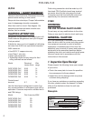
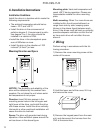
Mounting Direction and Space
NOTICE: The durability and reliability of the
drive will be affected by the ambient tem-
perature. Do not place the unit where ambi-
ent temperature is not proper.
Direction: Insert M4 size screws in the
mounting screw holes in the left upper and
right lower of the drive, and install the drive
with these screws. Install the drive vertically.
Horizontal or other positional installation will
cause the drive to overheat.
Space: The drive will generate heat during
operation. Allow sufficient space around the
unit as shown in the above figure.
PRG
RESET
FUNC
DATA
RUN
STOP
CLOSED
OPEN
FVR-C9S
3.94”
(10cm)
0.394”
(1cm)
3.94”
(10cm)
0.394”
(1cm)
PRG
RESET
FUNC
DATA
RUN
STOP
CLOSED
OPEN
FVR-C9S
Cover Mounting Screw
2
1
Side view of inverter