


13
FVR-C9S-7UX
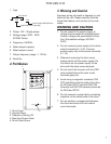
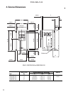
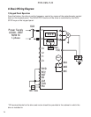
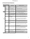
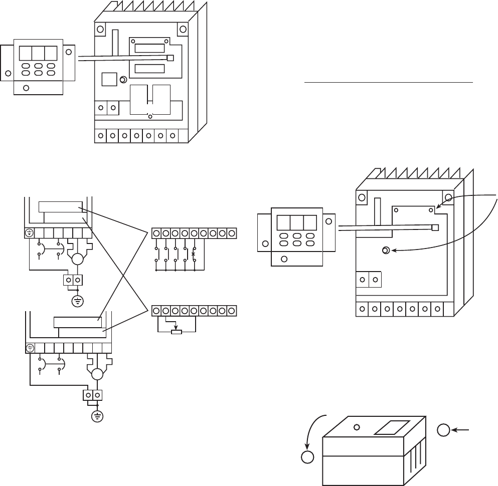
4) Arrange the main circuit and the control
circuit wiring as follows.
1. Motor coast-to-stop
2. Reset signal
3. Reverse-direction operation command
4. Forward-direction operation command
5. External alarm
6. Frequency setting VR
7. Combined alarm relay output
Note 1) FWD and THR are connected to CM
at the factory. In this condition,
starting/stopping can be performed
via RUN/STOP keys on the keypad
panel.
Note 2) In case of using an external potenti
ometer, remove the connector
which the keypad panel and the
CN2 on the drive main unit are
connected.
Note 3) Connect the power supply of over
voltage category II. If the power
supply is over voltage category III,
place the devices to limit the over
voltage below 2.5kV.
Required for CE Certification.
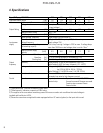
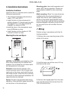
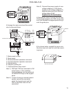
5) Reinstall the cover. Connect the harness
of the keypad panel to the CN2 on the main
unit, then reinstall the keypad panel fitting it
onto the guide pins.
6) As shown below, reinstall the cover onto
the drive main unit, and fix it with the mount-
ing screw.
1
B
X
3 5 7742
R
S
T
R
E
V
F
W
D
T
H
R
C
M
3
O
C
3
O
B
Note 1
6
1
1
6 76
1
2
1
3
F
M
3
O
A
Note 2
L1
L2 U V W
FVRF12C9S-7UX to FVR001C9S-7UX
Power Supply
3-Phase
motor
Cabinet PE
terminals
M
FVR002C9S-7UX
Power Supply
3-Phase
motor
Cabinet PE
terminals
M
L1 L2 U V W
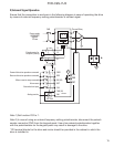
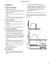
CN 2
CN 1
8. 8. 8.
Disconnect
CRG Lamp
CN 1
8. 8. 8.
Connect
CN 2 CN 2
Guide Pin
1
2
Side view of inverter