


19
FVR-C9S-7UX
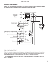
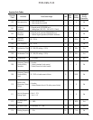
11. Operation
Pre-Operation Inspection
• Check for wiring errors.
• Check that all loose wire stands, metal
chips and unnecessary screws, etc. have
been removed.
• Check that no screws, terminals, etc. are
loose.
• Check that the wire ends of crimp terminal
are not in contact with other terminals.
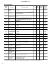
Test Run Check Points
• Smooth rotation and correct rotation
direction.
• No abnormal vibrations and noise from
the motor.
• Smooth acceleration and deceleration.
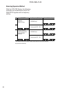
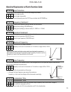
Frequency Setting Method
• Frequency setting by potentiometer con-
trol (factory preset at the time of ship-
ment; F01:1). As wired at the factory,
frequency setting can be performed by
turning the potentiometer control knob on
the keypad panel. Turn the potentiometer
control knob clockwise to increase fre-
quency.
• Frequency setting by digital signal (F01 :
0). With the function F01 set to 0, fre-
quency can be increased or decreased by
the
UP/DOWN) keys on the keypad panel.
UP: Frequency up
DOWN: Frequency down
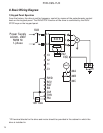
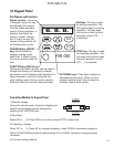
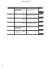
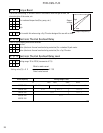
RUN/STOP Method
• RUN/STOP by keypad panel operation
(Factory preset at the time of shipment
F02:0).
• The drive is shipped with a factory in-
stalled jumper, between FWD-CM. Only
forward operation is possible. To enable
reverse operation, remove the jumper
from FWD/CM and install the jumper
between REV-CM.
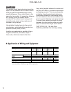
• RUN/STOP by terminal operation (F02 : 1)
Note: Open FWD and REV terminals when
changing F02 data. Data cannot be changed
if not open.
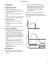
RUN
STOP
Time
Frequency
Forward
Reverse
FWD-CM
REV-CM
ON
ON
Frequency