


14
FVR-C9S-7UX
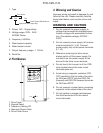
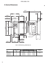
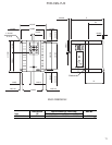
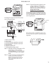
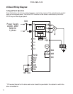
8. Basic Wiring Diagram
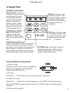
1) Keypad Panel Operation
From the factory, the drive is set for frequency control by means of the potentiometer control
knob on the keypad panel. The RUN/STOP function of the drive is controlled by the RUN/
STOP keys on the keypad panel.
* PE terminal blocks for the drive and motor should be provided in the cabinet in which the
drive is installed in.
M
FAB
8 8 8
CN2
10V 1mA
L1
L2
U
V
W
13
12
11
C1
FWD
REV
RST
BX
CM
THR
FM
Power Supply
AC220 - 240V
50/60 Hz
1-phase
30A
30B
30C
Fault
★
PE
E(G)