


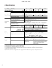

7
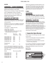
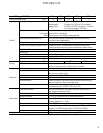
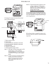
FVR-C9S-7UX
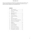
1. Type
2. Phase: 1AC - Single-phase
3. Voltage range: 220V - 240V
AC200V Series
4. Frequency: 50/60Hz
5. Rated output capacity
6. Rated output current
7. Output frequency range: 1- 120 Hz
8. Serial No.
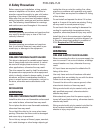
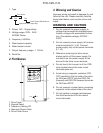
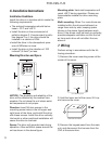
2. Part Names
1. Drive Cover
2. Keypad Panel
3. Frequency Setting VR
4. Mounting Screw Holes
5. Drive Cover Screw
PRG
RESET
FUNC
DATA
RUN
STOP
CLOSED
OPEN
FVR-C9S
1
2
4
3
5
4
F V R F 2 5 C 9 S 7 U X
Drive Series
Applicable motor output (Hp)
Power Series: 200V UX Series
3. Warning and Caution
Improper wiring will result in damage to, and
failure of the unit. Please carefully note the
items listed below, and use the unit as indi-
cated.
WARNING AND CAUTION
1. Do not connect the power supply to
voltage that exceeds the standard speci-
fication voltage with permissible fluctua-
tion. (Permissible voltage: AC220V -
240V)
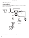
2. Do not connect power supply to the drive
output terminals (U, V, W). Connect
power supply only to the power terminals
(L1, L2)
3. Whenever removing the drive cover,
always switch off the power supply. Do
not switch on the power supply to the
drive with the drive cover removed.
4. Do not touch the live part until the CRG
lamp located above the main circuit
terminals goes out.
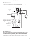
5. Avoid using a magnetic contactor (ON/
OFF) installed in the line side of the drive
for RUN and STOP. Use the FWD-CM
(forward) and REV-CM (reverse) terminals
for RUN and STOP.
6. Do not connect a power factor correcting
capacitor to the output side of the drive.
7. Do not perform a megger test between
the drive terminals or on the control
circuit terminals.