


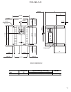
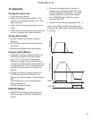
15
FVR-C9S-7UX
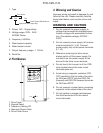
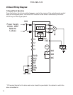
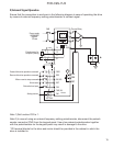
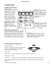
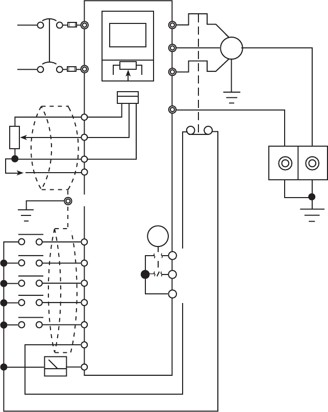
2) External Signal Operation
Ensure that the connection is as shown in the following diagram in case of operating the drive
by means of external frequency setting potentiometer or contact signal.
Note 1) Set function F02 to 1.
Note 2) In case of using an external frequency setting potentiometer, disconnect the potenti-
ometer connector (CN2) from the keypad panel. Use of an external potentiometer together
with the potentiometer on the keypad panel may result in damage to the drive.
* PE terminal blocks for the drive and motor should be provided in the cabinet in which the
drive is installed in.
Power supply
AC220-240V
50/60Hz
1 Phase
Potentiometer for
frequency setting
FAB
Thermal Relay
Forward-direction operation command
U
V
W
FM
THR (X1)
CM
RST
BX (X2)
REV
FWD
M
L1
L2
13
12
11
x
CN2
888
FVR-C9S
Reverse-direction operation command
Motor coast-to-stop command
External alarm input
Analog monitor
10V 1mA
Alarm reset
★
PE
30A
30B
30C
C1
Fault
E(G)
E(G)