


37
FVR-C9S-7UX
16. Electromagnetic Compatibility (EMC)
1. General
In accordance with the provisions described
in the European Commission Guidelines
Document on Council Directive 89/336/EEC,
Fuji Electric Co., Ltd. has chosen to classify
the FVR-C9S-7UX range of drives as “Com-
plex Components”. Classification as “Com-
plex Components” allows a product to be
treated as “apparatus”, and thus permits
compliance with the essential requirements
of the EMC Directive to be demonstrated to
both an integrator of FVR drives and to his
customer or the installer user. FVR drives up
to 2 Hp are supplied “CE-marked”, signifying
compliance with EC Directive 89/336/EEC
when fitted with specified filter units installed
and earthed in accordance with this sheet.
This specification requires the following
performance criteria to be met.
Immunity : EN50082-2
Emissions : EN50081-1
2. RFI Filters
It is strongly recommended that the appro-
priate FVR input filter is used, as shown in
the followings, to limit RF current flowing
into the main supply circuit. Without an input
filter a FVR installation may not meet statu-
tory requirement. FVR drives contain high
power semi-conductor devices which are
switched at high speeds to synthesis a near-
sinusoidal current waveform across the
frequency range of the output. Rapidly-
changing voltages and currents will generate
some degree of electromagnetic emission.
Emissions will be predominantly conducted
through the motor and the mains supply
cables, although some radiated emissions
will be detected in close proximity to the
drive system. It is essential that precautions
are taken both at the design stage and at the
time of installation to prevent radio fre-
quency interference (RFI) from the drive
system affecting sensitive equipment in
close proximity.
3. Recommended Installation Instructions
It is necessary that to conform to the EMC
Directive, these instructions must be fol-
lowed. Follow the usual safety procedures
when working with electrical equipment. All
electrical connections to the filter, drive and
motor must be made by a qualified electrical
technician.
1) Check the filter rating label to ensure that
the current, voltage rating and part number
are correct.
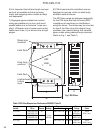
2) The back panel of the wiring cabinet of
board should be prepared for the mounting
dimensions of the filter. Care should be
taken to remove any paint etc. from the
mounting holes and face area around the
hole of the panel. This will ensure the best
possible earthing of the filter.
3) The filter should then be securely
mounted in position, and the drive mounted
to the front of the filter with the screws
provided.
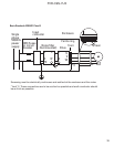
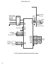
4) Connect the incoming mains supply to the
filter terminals marked “LINE” and earth any
cables to the earth stud provided. And fit the
Input Ferrite Ring (if required two ferrite
rings, refer to table 1), then connect the filter
terminals marked “LOAD” to the mains input
of the drive using short length of appropriate
gauge wire.
5) Fit the Output Ferrite Ring as close to the
drive as possible and connect the motor.
Armored or screened cable should be used
with the 3 phase conductors only passing
twice through the center of the Output Fer-
rite Ring. The earth conductor should be
securely earthed at both drive and motor
ends. The screen should be connected to
enclosure.