


Series 2040 Test System
Series 2040 Maintenance Manual V2.00Diagnostics
28
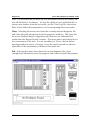
configuration table. From this utility, any system configuration may be
generated. It is the users responsibility to make sure the generated
configuration is valid.
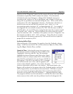
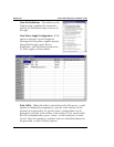
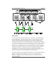
The Programmable variable power supplies (maximum of five) may be
defined in terms of maximum voltage and current once a
Programmable Power Supply is selected (up/down button). With Volts
or Amps selected, the jog shuttle located to the right modifies the
selected value. The option buttons under the jog shuttle control
determine what position in the serial loop that the supply being
defined occupies. However, the variable supplies must be filled in a
contiguous manner from #0 to #4. The spin control on the upper left
corner of the dialog is used to determine which programming channel
is being configured.
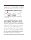
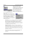
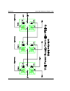
If a GPIB or HPIB power supply is being defined or added, the channel
and type can be selected and the upper right of the dialog changes to
allow the programmer to select a power supply type, a GPIB/HPIB
Device number, and what Relay Control board will be used. The spin
control on the middle left of the dialog (Patchboard Connection) is
used to define which of the five Patchboard connections are connected
to which supply, or if a GPIB/HPIB supply will use an external output
(i.e. the supply’s output does not physically appear on the Patchboard.)
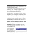
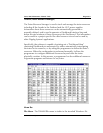
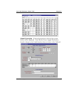
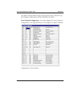
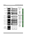
The rest of the Testhead is displayed in table format by slot number.
The Description and Board Number drop-down menus are directly
linked to, and will modify the table. The Clear All button will clear all
configuration items.
Board Codes are specific identifiers for the particular type of board
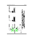
selected for that slot. Board Numbers are used to define the resources
of that particular board. For example, if there are two of the same type
of board in the system, board numbers zero and one, the resources of
board one will be numbered over and above those of board number
zero. In other words, for a Relay Multiplexer Board containing sixty-
four channels, board zero channels would be labeled zero through
sixty-three and board one channels would be labeled sixty-four
through one hundred and twenty-seven.