


Series 2040 Test System
Series 2040 Maintenance Manual V2.00 Diagnostics
39
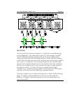
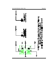
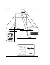
1) Verify on the relay controller board (0000-5X44) that pin #3 relative
to pin #4 of connector P3 (PSC Port) is low or at a logic “0.” If not, a
problem exists on the PSC board, in the fault/inhibit cable from the
PSC board to connector P3, or with connector P3 .
2) Otherwise, verify that pin #3 relative to pin #4 of connector P5
which mates to the first relay disconnect board is low or at a logic “0.”
If not, a problem exists on the relay controller board.
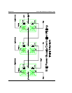
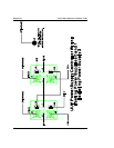
3) Otherwise, on the first relay disconnect board, verify that pin #3
relative to pin #4 of connector P1 (which mates to the relay controller
board) is low or at a logic “0.” If not, a problem exists either with
connector P1 or else with connector P5 on the relay controller board.
4) Otherwise, verify that pin #3 relative to pin #4 of connector P3
(which mates to the next relay disconnect board) is low or at a logic
“0.” If not, a problem exists between connectors P1 and P3 on the
relay disconnect board.
5) Otherwise, on the second relay disconnect board, verify that pin #3
relative to pin #4 of connector P1 (which mates to the first relay
disconnect board) is low or at a logic “0.” If not, a problem exists either
with connector P1 or else with connector P3 on the first relay
disconnect board.
6) Repeat steps #4-5 for the second and all subsequent relay
disconnect boards up to and including the last relay disconnect board.
7) Jumper shunts #7-8 (which connect the corresponding inhibit and
fault signals) on the last relay disconnect board must be installed. Verify
continuity from pin #3 of connector P1 through jumper shunt #8 to
pin #4 of connector P2 (which connects to the fault/inhibit cable for
the HP power supply). Verify continuity from pin #4 of connector P1
through jumper shunt #7 to pin #3 of connector P2.
8) Otherwise, verify that pin #4 relative to pin #3 of connector P2 is
low or at a logic “0.” If not, a problem exists on the relay disconnect
board, in its fault/inhibit cable, or with the HP power supply’s inhibit
input pins. Verify the continuity of each wire in the fault/inhibit cable,