


Series 2040 Test System
Series 2040 Maintenance Manual V2.00Module Repair and Replacement
66
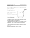
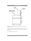
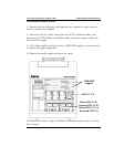
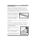
1. Remove the termination from the rear of the spring. (Remove the Testhead
card.)
2. With a slow and steady pressure, bend the one side of the “U” in far
enough to clear the board opening. Then, in the same manner, bend the other
side of the “U” in far enough to permit the contact spring to pass freely though
the board cavity.
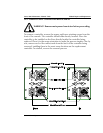
CAUTION: To prevent chipping of the cavity, double check that the “U” will
clear the cavity opening.
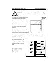
3. Face the front of the board, and grasp the damaged contact spring across
the chevron with a needle-nosed pliers. With a steady, even pressure, pull
straight out on the contact spring until it is free and clear of the board - and
then destroy the contact spring
immediately!
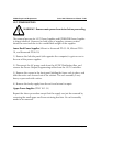
To install a new contact spring in the board, the following steps are
recommended:
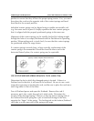
1. Be sure that you have the proper contact spring, right hand or left hand,
whichever is required (the chevron contact area should be facing the general
direction of the bottom left or bottom right corner of the frame).
2. The Digalog part numbers for the springs are as follows:
Right Hand: 2825-1011
Left Hand: 2825-1012
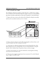
3. Orient and start the contact spring by hand, according to the position of the
“D” within the board cavity.
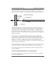
4. Place the end of a medium size screwdriver against the end of the barrel, at
the base of the blade. Then press with a slow and even pressure until the
“ears” are seated on the board. As the “ears” reach the surface of the board,
you will feel the locking tab snap into the locked position.
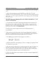
5. Check the replacement contact spring to see that it is properly aligned with
the adjacent springs.