Series 2040 Test System
Series 2040 Maintenance Manual V2.00Diagnostics
40
and verify that each wire is connected to the proper terminal on the HP
power supply. The HP power supply may be configured to use its
inhibit input pins as simply digital I/O pins. Consult its operating
manual to determine the correct position of the internal configuration
jumper shunt for “Fault/Inhibit” operations, and then remove its cover
to confirm the shunt’s proper placement.
9) Otherwise, verify that an arrow exists above the word “Prot” on the
LCD display. If not, the HP power supply itself is faulty.
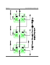
10) Otherwise, verify that pin #1 relative to pin #2 of connector P2 on
the relay disconnect board is low or at a logic “0.” If not, a problem
exists in the HP power supply, in the fault/inhibit cable for this supply,
on the relay disconnect board for this supply, on the relay disconnect
board for the previous supply, in the fault/inhibit cable for the previous
supply, or in the previous HP power supply itself.
11) Otherwise, verify that pin #1 relative to pin #2 of connector P1
(which mates to the previous relay disconnect board) is low or at a logic
“0.” If not, a (continuity?) problem exists on the relay disconnect board.
12) Otherwise, on the previous relay disconnect board, verify that pin
#1 relative to pin #2 of connector P3 (which mates to the next relay
disconnect board) is low or at a logic “0.” If not, a problem exists either
with connector P3 or else with connector P1 on the next relay
disconnect board.
13) Repeat steps #8-12 for each previous relay disconnect board up to
and including the first relay disconnect board.
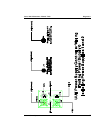
14) Otherwise, on the relay controller board, verify that pin #1 relative
to pin #2 of connector P5 (which mates to the first relay disconnect
board) is low or at a logic “0.” If not, a problem exists either with
connector P5 or else with connector P1 on the first relay disconnect
board.
15) Otherwise, verify that pin #1 relative to pin #2 of connector P1
(PSC Port) is low or at a logic “0.” If not, a problem exists on the relay
controller board, in the fault/inhibit cable from the PSC board, or on


