


Series 2040 Test System
Series 2040 Maintenance Manual V2.00 Module Repair and Replacement
65
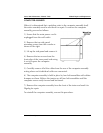
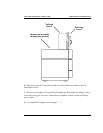
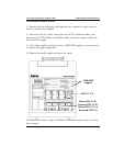
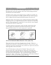
Plunger
Patchboard
“D” shaped sleeve
“D”shaped
latching tab
Board Side of Patchboard
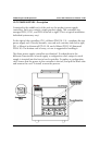
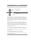
Retract the plunger of the spring removal tool and position the sleeve of the
tool so that the flat side of the “D”-shape formed by the end of the sleeve is
aligned with the latching tab of the damaged Patchboard spring (Testhead card
side of the Patchboard). Carefully lower the sleeve over the spring until it is
fully seated and the sleeve is resting against the Patchboard. The “stinger” of
the spring will slide into the hollow end of the plunger. A flashlight may be
needed to provide adequate lighting, especially if there are Testhead cards on
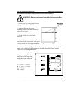
either side of the slot. The latching tab of the spring should be fully depressed
inside the tool sleeve.
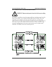
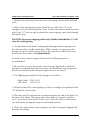
Be sure that the tool is held straight in-line with the spring. Apply steady,
careful pressure on the handle. Do NOT push sharply and do NOT strike or
tap the end of the handle. Resistance will be felt as the spring slides out of the
Patchboard. Continue to apply steady pressure until the plunger handle
bottoms out. If these precautions are ignored, it is possible to damage the tool
or the Patchboard material itself.
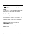
The ejected Patchboard spring will be protruding from the top (fixture mating)
side of the Patchboard. Simply grasp it and pull it free of the Patchboard.
After replacing the spring in the Patchboard, re-install the Testhead card and
close the Testhead.
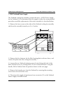
CONTACT SPRING REPLACEMENT (Conventional Method)
To remove a damaged contact spring when the removal tool is not available,
use the following procedure: