


Series 2040 Test System
Series 2040 Maintenance Manual V2.00Module Repair and Replacement
64
position to ensure that they all have the proper spring tension. If so, you must
then place the comb on the opposite side of the contact springs and bend
them back to the normal position.
Individual contact springs can be aligned using a suitable non-metallic tool
(e.g. the eraser end of a pencil). Simply reposition the bent contact spring so
that it is aligned with the properly positioned springs in the same row.
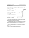
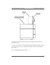
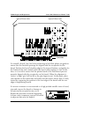
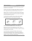
Alignment of the contact springs can be visually checked by looking straight
through the holes of an empty Patchboard with the Patchboard in operating
position. When making such a visual check, be sure that the contact springs
are positioned within the range shown.
If a contact spring is severely bent, or bent vertically, replacement of the
contact spring is recommended. Should the bend be minor and in the
horizontal (lateral) plane, the contact spring may be repairable.
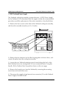
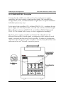
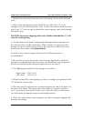
USE OF PATCHBOARD SPRING REMOVAL TOOL (0000-2746)
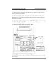
Determine the slot in which the damaged spring is located. If there is a
Testhead card in that slot, it will need to be removed. Be sure to use a wrist
strap when removing or inserting the card, and be sure to place the card into a
static bag while it is out of the tester.
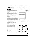
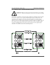
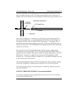
Turn off Testhead power and open the Testhead. Remove the card if
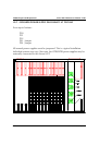
necessary, put it into a static bag and set it safely aside. Determine the
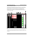
location of the damaged spring. Observe on the top (fixture mating) side of
the Testhead that each spring has a pair of small metal tangs at the base,
opposite the “finger” of the spring. The latching tab on the bottom (Testhead
card) side is on the same side of the spring as the tangs.