


Series 2040 Test System
Series 2040 Maintenance Manual V2.00Diagnostics
38
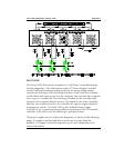
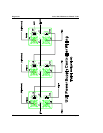
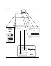
For a system containing “n” number of HP power supplies, the PSC board
drives the +Inhibit (input) line of HP P/S #n low relative to its -Inhibit (input)
line. When this power supply detects that its +Inhibit input signal is low, then
it drives its +Fault (output) signal low relative to its -Fault (output) signal.
These fault output lines are connected to the inhibit input connections of HP
P/S #(n-1). Upon its detection that HP P/S #n has driven its +Inhibit (input)
signal low, HP P/S #(n-1) will then “fault” HP P/S #(n-2) using its fault (output)
connections. Thus, each HP P/S in the fault loop will “fault” the power supply
preceding it in the loop all the way to HP P/S #0. The Fault (output) lines of
HP P/S #0 connect to the PSC board, which allows that power supply to
signal the PSC board that an error has been detected by one of the HP power
supplies.
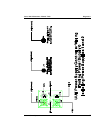
Upon detection of an internal error condition, such as overvoltage, or the
external inhibit (input) signal, the HP power supply will program its output(s)
to 0.0V @ 0.0A, disable its output(s), and assert its fault (output) signal.
If an HP power supply detects an internal error condition, it will then drive its
+Fault (output) line low to signal the next HP power supply positioned below
it in the loop. Eventually, the “fault” signal will reach HP P/S #0, and it, in
turn, will trigger the PSC board. The PSC board will then latch HP P/S fault
condition and drive all of its fault output connections, including that for the
HP power supplies. This will “fault” all of the HP power supplies positioned
after the one which detected the internal error condition. The initial faulting
HP power supply will also have its +Inhibit (input) connection driven low by
the power supply following it.
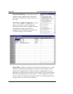
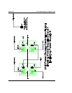
To determine which HP power supply detected an internal error condition,
press the “Local” button and then the “Prot” button on each HP power
supply. All of the HP power supplies that were “faulted” by their following
brethen via their inhibit (input) lines will display the letters “RI,” which stands
for “Remote Inhibit,” in its LCD display. The single HP power supply that
displays something other than “RI” in its LCD display is the power supply that
detected an internal error condition. Consult its operating manual to
determine the cause of the internal error condition.
If some or none of the HP power supplies are disabled via their fault/inhibit
loop connections when the PSC board detects a fault from some other source,
such as the proximity switch, proceed with the following troubleshooting
procedure.