


2-5
Installing the Series 2300 and 2500 Switches
Installation Procedures
Installing the Series 2300
and 2500 Switches
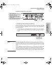
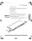
■ Installation Location - Before installing the switch, plan its location and
orientation relative to other devices and equipment:
• In the front of the switch, leave at least 7.6 cm (3 inches) of space for
the twisted-pair and fiber-optic cabling.
• In the back of the switch, leave at least 3.8 cm (1 1/2 inches) of space
for the power cord.
• On the sides of the switch, leave at least 7.6 cm (3 inches) for cooling,
except if the switch is installed in an open EIA/TIA rack.
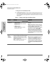
Fiber Optic Cables
100Base-FX
(on the 100-FX
Transceiver)
62.5/125 µm or 50/125 µm core/cladding
diameter, graded-index, multimode fiber-optic
cables that are fitted with SC connectors
• 2 kilometers for full-duplex connections
Gigabit-SX
(on the
Gigabit-SX
transceivers)
62.5/125 µm or 50/125 µm core/cladding
diameter, graded-index, multimode fiber-optic
cables that are fitted with SC connectors
• 62.5 µm cable:
– 160 MHz*km = 220 meters
– 200 MHz*km = 275 meters
• 50 µm cable:
– 400 MHz*km = 500 meters
– 500 MHz*km = 550 meters
Gigabit-LX
(on the
Gigabit-LX
transceivers)
Single-mode cables fitted with SC connectors.
62.5/125 µm or 50/125 µm core/cladding
diameter, graded-index, multimode fiber-optic
cables may also be used, but a mode
conditioning patch cord may be needed — see
the Installation Guide that came with the
transceiver for more information.
• single-mode cable - 5 kilometers
• multimode cable - 550 meters
Port Type Cable Type Length Limits
2353-ed2.book Page 5 Friday, February 9, 2001 6:00 PM