2 – Index
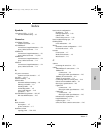
Index
cables, twisted pair
category 3, 4, 5 … B-4
cross-over cable pin-out … B-6
MDI-X to MDI connections … B-5, B-7
MDI-X to MDI-X connections … B-6
pin-outs … B-5, B-7
straight-through cable pin-out … B-5, B-7
switch-to-computer connection … B-5, B-7
switch-to-switch or hub connection … B-6
cables, twisted-pair
HP Auto-MDIX feature … B-3
specifications … B-2
wiring rules … B-4
cables, twisted-pair connector pin-outs … B-3
cabling infrastructure … 2-4
Clear button
deleting passwords … 1-7
description … 1-7
location on switch … 1-2, 1-7
restoring factory default configuration … 1-7,
3-11
to delete password protection … 2-19
CLI prompt, console
displaying … 2-16
configuration
checking when troubleshooting … 3-3
DHCP/Bootp … 2-17
full duplex only for transceivers … 2-6
IP address … 2-18
IP address, manually … 2-18
manager password … 2-18
restoring factory defaults … 1-7, 3-11
subnet mask … 2-18
Switch Setup screen … 2-18
connecting the switch to a power source … 2-13
connector specifications … A-2
console
checking messages during
troubleshooting … 3-9
displaying the CLI prompt … 2-16
features … 2-15
how to connect in-band … 2-15
how to connect out-of-band … 2-15
serial cable connection … 2-16
Switch Setup screen … 2-18
telnet access … 2-20
terminal configuration … 2-15
console port
description … 1-6
location on switch … 1-2, 1-6
cross-over cable
pin-out … B-6
D
deleting passwords … 1-7
description
back of switch … 1-7
front of switch … 1-2
LEDs … 1-3
switch … 1-1
desktop switch
sample topology … 2-22
DHCP
automatic switch configuration … 2-17
for in-band access … 2-15
diagnostic tests … 3-9
checking the console messages … 3-9
checking the LEDs … 3-9
end-to-end connectivity … 3-10
testing the switch only … 3-9
testing twisted-pair cabling … 3-10
download port
description … 1-6
location on the switch … 1-6
downloading new code, Series 2300 switches … 3-12
E
electrical specifications, switch … A-1
EMC regulatory statements … C-8
environmental specifications, switch … A-1
F
factory default configuration, restoring … 1-7, 3-11
Fan Status LED … 1-3
Fault LED … 1-3
behavior during self test … 2-8
behaviors … 1-3
blinking definition … 1-3
location on switch … 1-2
showing error conditions … 3-4
FDx LED … 1-3, 1-5
2353-ed2.book Page 2 Friday, February 9, 2001 6:00 PM


