


iv HP OmniBook 4100
Figures
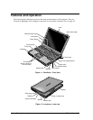
Figure 1-1. OmniBook - Front View....................................................................................................1-2
Figure 1-2. OmniBook - Side View .....................................................................................................1-2
Figure 1-3. OmniBook - Rear View.....................................................................................................1-3
Figure 1-4. Replaceable Module Diagram......................................................................................... 1-12
Figure 2-1. Removing the Battery or Plug-In Module .........................................................................2-3
Figure 2-2. Removing a RAM Board...................................................................................................2-4
Figure 2-3. Removing the Hard Disk Drive.........................................................................................2-5
Figure 2-4. Installing a Hard Drive in the Cover .................................................................................2-6
Figure 2-5. Removing the Keyboard....................................................................................................2-8
Figure 2-6. Removing the Display.....................................................................................................2-10
Figure 2-7. Removing the Display.....................................................................................................2-13
Figure 2-8. Removing the Top Case ..................................................................................................2-15
Figure 2-9. Removing the Motherboard.............................................................................................2-17
Figure 2-10. Installing Docking Doors and Module Latch ................................................................2-19
Figure 2-11. Positioning Thermal Pads.............................................................................................2-19
Figure 2-12. Removing the BIOS IC .................................................................................................2-20
Figure 3-1. Basic Troubleshooting Steps.............................................................................................3-2
Figure 3-2. OmniBook Diagnostic Screens — Basic and Advanced.................................................3-12
Figure 3-3. Serial and Parallel Loopback Connectors........................................................................3-14
Figure 3-4. DMI Components............................................................................................................3-22
Figure 4-1. Exploded View..................................................................................................................4-2
Figure 4-2. Display Components .........................................................................................................4-5
Figure 4-3. Motherboard Components.................................................................................................4-6
Tables
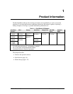
Table 1-1. OmniBook 4100 Models ....................................................................................................1-1
Table 1-2. Product Comparisons..........................................................................................................1-3
Table 1-3. Activating Power Modes ....................................................................................................1-4
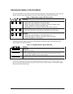
Table 1-4. Main Status Lights (LED Strip Cable) ...............................................................................1-5
Table 1-5. Keyboard Status Lights (VGA PCA) .................................................................................1-5
Table 1-6. Fn Hot Keys........................................................................................................................1-6
Table 1-7. System Interrupts................................................................................................................1-7
Table 1-8. System Memory..................................................................................................................1-7
Table 1-9. System Input/Output Addresses (100-3FF) ........................................................................1-8
Table 1-10. DMA Channels.................................................................................................................1-8
Table 1-11. OmniBook 4100 Specifications........................................................................................1-9
Table 1-12. OmniBook 4100 Accessories .........................................................................................1-11
Table 1-13. Functional Structure........................................................................................................1-13
Table 2-1. Removal Cross-Reference ..................................................................................................2-1
Table 2-2. Required Equipment...........................................................................................................2-2
Table 2-3. Recommended Screw Torques ........................................................................................... 2-2
Table 2-4. RAM Board Replacement Part Numbers ...........................................................................2-4
Table 2-5. Hard Disk Drive Replacement Part Numbers.....................................................................2-5
Table 2-6. Replacing Small Parts (User-Replaceable).........................................................................2-7
Table 2-7. Display Component Compatibility ...................................................................................2-11
Table 2-8. Removing Display Components.......................................................................................2-21
Table 2-9. Removing Top Case Components ....................................................................................2-23
Table 2-10. Removing Bottom Case Components.............................................................................2-23
Table 3-1. Scope of Diagnostic Tools..................................................................................................3-4