


2-24 Removal and Replacement HP OmniBook 4100
Component Removal Procedures Additional Steps (See figures on pages 4-2, 4-6)
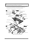
CPU Bottom Plate
Keyboard (page 2-8). 1. Remove the screw from the heatsink cover and lift
it off the heatpipe.
2. Remove the screws from the CPU top plate, then
lift the right half of the complete CPU assembly so
it unplugs from the motherboard.
3. Slide off the top plate, then remove the CPU
module from the bottom plate.
Reassembly Notes: Assemble the CPU module, top
plate, and bottom plate before installing them on the
motherboard.
Caution: Keep the CPU assembly flat while installing
it. Press it down above the connectors at the right end.
Otherwise, you could damage the connectors.
CPU Module (MMO)
Keyboard (page 2-8). 1. Remove the screw from the heatsink cover and lift
it off the heatpipe.
2. Remove the screws from the CPU top plate, then
lift the right half of the complete CPU assembly so
it unplugs from the motherboard.
3. Slide off the top plate, then remove the CPU
module from the bottom plate.
Reassembly Notes: Assemble the CPU module, top
plate, and bottom plate before installing them on the
motherboard.
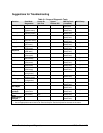
Caution: Replace the CPU module with one of the
same module type—see the table on page 4-3.
Caution: Install or replace CPU module thermal pads
that are missing or damaged—see the picture on page
2-19.
Caution: Keep the CPU assembly flat while installing
it. Press it down above the connectors at the right end.
Otherwise, you could damage the connectors.
CPU Top Plate
Keyboard (page 2-8). 1. Remove the screw from the heatsink cover and lift
it off the heatpipe.
2. Remove the screws from the CPU top plate and
remove the top plate.
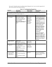
Caution: Replace the top plate with one that is
compatible with the CPU module—see the table on
page 4-3.
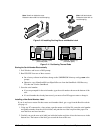
DC-DC PCA
Plug-in module (page 2-3).
Hard drive (page 2-5).
Keyboard (page 2-8).
Display (page 2-10).
Top case (page 2-14).
1. Remove the screw from the IR PCA and move the
PCA aside.
2. Remove the two screws from the right frame and
remove the frame.
3. Unplug the DC-DC PCA.
Fan
Keyboard (page 2-8).
Display (page 2-10).
1. Remove the screw from the plastic cover and
remove the cover.
2. Unplug the fan cable from the motherboard and lift
out the fan.
Reassembly Notes: Route the fan wires at the bottom
of the opening next to the motherboard.