


HP OmniBook 4100 Removal and Replacement 2-23
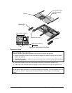
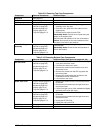
Table 2-9. Removing Top Case Components
Component Removal Procedures Additional Steps
Keyboard
See page 2-8.
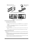
Strip Cover
Display (page 2-10). Unsnap the strip cover from the hinge covers.
Top Case
See page 2-14.
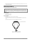
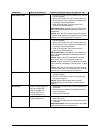
Touch-Pad Flex Cable
Plug-in module (page 2-3).
Hard drive (page 2-5).
Keyboard (page 2-8).
Display (page 2-10).
Top case (page 2-14).
1. Remove the two screws holding the support
assembly to the top case.
2. Peel off the four pads of the flex cable from the
support plate.
3. Release the flex cable from the PCA.
Reassembly Notes: Position the four pads using the
bumps on the support plate.
Check the feel and operation of all four click buttons.
Caution: Do not press on the round switches on the
four pads. Press next to the switches.
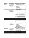
Touch-Pad Support
Assembly
Plug-in module (page 2-3).
Hard drive (page 2-5).
Keyboard (page 2-8).
Display (page 2-10).
Top case (page 2-14).
Remove the two screws holding the support assembly
to the top case.
Reassembly Notes: Check the feel and operation of
all four click buttons.
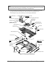
Table 2-10. Removing Bottom Case Components
Component Removal Procedures Additional Steps (See figures on pages 4-2, 4-6)
Air Vent Cover
Plug-in module (page 2-3).
Hard drive (page 2-5).
Keyboard (page 2-8).
Display (page 2-10).
Top case (page 2-14).
1. Remove the screw from the plastic heat exchange
cover and remove the cover.
2. Lift off the fan and move it aside.
3. Remove the screw from the heatsink cover and
remove the cover.
4. Remove the screws from the CPU top plate and
remove the plate.
5. Remove the screw holding the left frame to the
motherboard and lift off the frame.
6. Lift out the air vent cover.
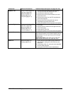
Audio Jack Cover
Plug-in module (page 2-3).
Hard drive (page 2-5).
Keyboard (page 2-8).
Display (page 2-10).
Top case (page 2-14).
1. Remove the screw from the IR PCA and move the
PCA aside.
2. Remove the two screws from the right frame and
remove the frame.
3. Lift the front-right corner of the motherboard slightly
and remove the audio jack cover.
Audio Jack PCA
Plug-in module (page 2-3).
Hard drive (page 2-5).
Keyboard (page 2-8).
Display (page 2-10).
Top case (page 2-14).
1. Remove the screw from the IR PCA and move the
PCA aside.
2. Remove the two screws from the right frame and
remove the frame.
3. Unplug the DC-DC PCA.
4. Unplug the audio jack PCA.
BIOS IC
See page 2-19.
Bottom Case
See page 2-16.