


HP OmniBook 4100 Removal and Replacement 2-25
Component Removal Procedures Additional Steps (See figures on pages 4-2, 4-6)
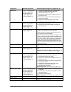
Frame, Left
Plug-in module (page 2-3).
Hard drive (page 2-5).
Keyboard (page 2-8).
Display (page 2-10).
Top case (page 2-14).
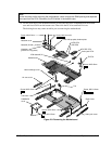
1. Remove the screw holding the heat exchange
cover to the frame and remove the cover.
2. Lift off the fan and move it aside.
3. Remove the screw from the heatsink cover and
remove the cover.
4. Remove the screws from the CPU top plate and
remove the top plate.
5. Remove the screw holding the frame to the
motherboard and remove the frame.
Frame, Left or Right
Plug-in module (page 2-3).
Hard drive (page 2-5).
Keyboard (page 2-8).
Display (page 2-10).
Top case (page 2-14).
1. Remove the screw holding the IR PCA to the frame
and move the PCA aside.
2. Remove the two screws holding the frame and
remove the frame.
Heatsink Parts
Keyboard (page 2-8).
Display (page 2-10).
• Heat exchange cover: Remove the screw from the
plastic cover and remove it from the frame.
• Heatsink cover: Remove the screw from the cover
and remove it from the heatpipe.
• Finned heatsink: Remove the top case (page 2-14).
Remove the screw holding the heat exchange cover
to the frame and remove the cover. Lift off the fan
and move it aside. Remove the screw and heatsink
cover, then remove the screws from the CPU top
plate and remove the top plate. Remove the screw
from the left frame and lift off the frame. Then lift out
the finned heatsink.
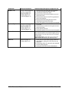
IR PCA
Display (page 2-10). Remove the screw from the IR PCA, then unplug the
cable from the motherboard.
LVDS PCA
Keyboard (page 2-8).
Display (page 2-10).
Use a probe to unplug the LVDS PCA from the VGA
PCA.
Caution: The LVDS PCA must be compatible with the
LCD module. See the compatibility table on page
2-11.
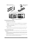
Module Latch, Left
Plug-in module (page 2-3).
Hard drive (page 2-5).
Keyboard (page 2-8).
Display (page 2-10).
Top case (page 2-14).
1. Remove the screw holding the heat exchange
cover to the frame and remove the cover.
2. Lift off the fan and move it aside.
3. Remove the screw from the heatsink cover and
remove the cover.
4. Remove the screws from the CPU top plate and
remove the top plate.
5. Remove the screw holding the frame to the
motherboard and remove the frame.
6. Lift off the latch and spring.
Reassembly Notes: See the picture on page 2-19.
Module Latch, Right
Plug-in module (page 2-3).
Hard drive (page 2-5).
Keyboard (page 2-8).
Display (page 2-10).
Top case (page 2-14).
1. Remove the screw from the IR PCA and move the
PCA aside.
2. Remove the two screws from the right frame and
remove the frame.
3. Lift off the latch and spring.
Reassembly Notes: See the picture on page 2-19.
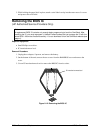
Motherboard
See page 2-16.
PCMCIA Socket
Keyboard (page 2-8). Remove the four screws from the PCMCIA socket and
unplug it from the motherboard.