


IP Routing Features
Configuring OSPF
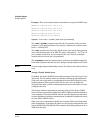
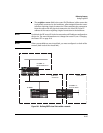
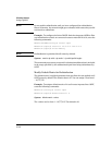
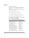
Example. Figure 16-1 shows an OSPF area border router, Routing
Switch-A, that is cut off from the backbone area (Area 0). To provide backbone
access to Routing Switch-A, you can add a virtual link between Routing
Switch-A and Routing Switch-C using Area 1 as a transit area. To configure the
virtual link, you define the link on the router that is at each end of the link. No
configuration for the virtual link is required on the routers in the transit area.
To define the virtual link on Routing Switch-A, enter the following commands:
HPswitch(ospf)# area 1 virtual-link 209.157.22.1
HPswitch(ospf)# write memory
Enter the following commands to configure the virtual link on Routing
Switch-C:
HPswitch(ospf)# area 1 virtual-link 10.0.0.1
HPswitch(ospf)# write memory
Syntax: area <ip-addr> | <num> virtual-link <router-id>
[authentication-key | dead-interval | hello-interval | retransmit-interval | transmit-
delay <value>]
The area <ip-addr> | <num> parameter specifies the transit area.
The <router-id> parameter specifies the router ID of the OSPF router at the
remote end of the virtual link. To display the router ID on an HP Series 5300XL
Switch, enter the show ip command.
See “Modify Virtual Link Parameters” below for descriptions of the optional
parameters.
Modify Virtual Link Parameters
OSPF has some parameters that you can modify for virtual links. Notice that
these are a subset of the parameters that you can modify for physical inter-
faces. cost is not configured for virtual links, it is calculated by route calcula-
tion.
You can modify default values for virtual links using the following CLI
command at the OSPF router level of the CLI, as shown in the following
syntax:
Syntax: area <num> | <ip-addr> virtual-link <ip-addr> [authentication-key
<string>] [dead-interval <num>] [hello-interval <num>] [retransmit-interval <num>]
[transmit-delay <num>]
16-46