


3-1 TURN-ON CHECKOUT PROCEDURE
TM 11-6625-2965-14&P
SECTION Ill
OPERATING INSTRUCTIONS
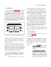
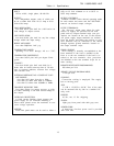
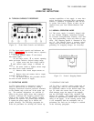
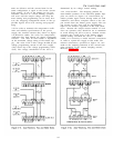
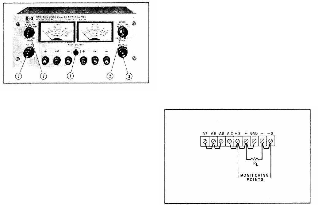
Figure 3-1.
Front Panel Controls and Indicators
3-2 The front panel controls and indicators are
shown in Figure 3-1.
The normal turn-on sequence,
is described below:
A. Push ON/OFF button
① and observe
that button lights,
B. Set range switch
② to desired operating
mode and meter switch to desired voltage range.
C. Adjust coarse and fine voltage controls
③ until desired output voltage is indicated on
meter.
D.
and short
E.
meter.
F.
terminals
G.
be used for both sections of supply.
Set meter switch to highest current range
circuit output terminals.
Observe short circuit output current on
Remove short and connect load to output
(front or rear),
For Model 6205B, this procedure should
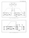
3-3 OPERATING MODES
3-4 The power supply is designed so that its
mode of operation can be selected by making
strapping connections between particular terminals
on the terminal strip at the rear of the power sup-
ply.
The terminal designations are stenciled in
white on the power supply above their respective
terminals. Although the strapping patterns illus-
trated in this section show the positive terminal
grounded, the operator can ground either termina1
or operate the power supply up to 300Vdc off
ground (floating). The following paragraphs de-
scribe the procedures for utilizing the various op-
erational capabilities of the supply. A more theo-
retical description concerning these operational
features is contained in Application Note 90 and
in various Tech Letters. Copies of these can be
obtained from your local Hewlett-Packard field
office,
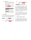
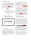
3-5 NORMAL OPERATING MODE
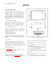
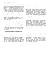
3-6 The power supply is normally shipped with
its rear terminal strapping connections arranged
for Constant Voltage/Current Limiting, local sens-
ing, local programming, single unit mode of oper-
ation. This strapping pattern is illustrated in Fig-
ure 3-2. The operator selects a constant voltage
output using the front panel controls (local pro-
gramming, no strapping changes are necessary).
Figure 3-2.
Norma 1 Strapping Pattern
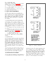
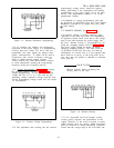
3-7 CONSTANT VOLTAGE
3-8 To select a constant voltage output turn on
the supply and, with no load connected, adjust
the VOLTAGE controls for the desired output volt-
age. To check the current limit, connect an ex-
ternal ammeter across the output of the
supply,
turn the VOLTAGE controls fully clockwise, and
observe the reading.
The current limit is factory
adjusted to approximately 100mA above the current
rating of the supply.
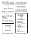
If the existing current limit
is not compatible with the anticipated load re-
quirements, the limit can be changed as outlined
in the following paragraphs.
3-1