


TM 11-6625-2965-14&P
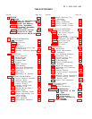
LIST OF ILLUSTRATIONS
Figure
2-1
2-2
2-3
2-4
3-1
3-2
3-3
3-4
3-5
3-6
3-7
3-8
3-9
3-10
4-1
Page No.
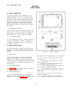
Outline Diagram 2-1
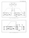
Rack Mounting, Two Units 2-2
Rack Mounting, One Unit 2-2
Primary Connections 2-3
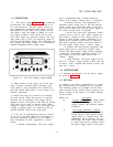
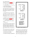
Front Panel Controls and Indicators 3-1
Normal Strapping Pattern
3-1
Current Limit Alteration
3-2
Remote Resistance Programming 3-3
Remote Voltage Programming
3-3
Remote Sensing 3-3
Norma I Series Connections 3-4
Auto-Series, Two and Three Units 3-4
Auto-Parallel, Two and Three
Units
3-5
Auto-Tracking, Two and Three
Units 3-5
Overa11 Block Diagram 4-1
Figure
4-2
5-1
5-2
5-3
5-4
5-5
5-6
5-7
5-8
5-9
5-10
5-11
Page No.
Multiple Range Meter Circuit,
Simplified Schematic
4-4
Front Panel Terminal Connections 5-1
Output Current Measurement
Technique
5-1
Differential Voltmeter Substitute,
Test Setup
5-2
Output Current, Test Setup 5-4
Load Regulation, Test Setup
5-4
CV Ripple and Noise, Test Setup 5-5
CV Noise Spike, Test Setup
5-6
Transient Recovery Time,
Test Setup
5-7
Transient Recovery Time,
Waveforms
5-7
Output Impedance, Test Setup
5-8
Servicing Printed Wiring Boards
5-14
LIST OF TABLES
Table
Page No.
1-1 Specifications
1-3
5-1 Test Equipment Required
5-2
5-2 Reference Circuit Troubleshooting
5-9
5-3 Overall Trouble shooting 5-9
5-4 High Output Voltage Troubleshooting
5-11
5-5 Low Output Voltage Troubleshooting
5-11
5-6 Selected Semiconductor Characteristics
5-12
5-7 Checks and Adjustments After Replacement of Semiconductor Devices 5-12
6-1 Reference Designators
6-1
6-2 Description Abbreviations
6-1
6-3 Code List of Manufacturers
6-2
6-4 Replaceable Parts
6-5
iii