


TM 11-6625-2965-14&P
c.
Set METER switch to highest voltage
range and RANGE switch to highest voltage mode
and turn on supply.
d. Adjust VOLTAGE controls until front panel
meter indicates exactly the maximum rated output
voltage.
e. Differential voltmeter should indicate
maximum rated output voltage within 3%.
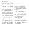
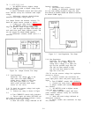
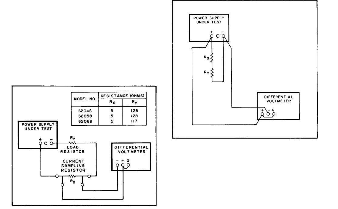
5-16 Output Current and Ammeter Accuracy. To
check the output current, proceed as follows:
a.
Connect test setup shown in Figure 5-4.
b.
Set METER switch to lowest current
range and RANGE switch to high voltage mode.
c.
Turn on supply and adjust VOLTAGE con-
trols until front panel meter indicates exactly 300
mA (0.5 Ampere for Model 6206B supplies).
d. Differential voltmeter should read 1.5 ±
0.045Vdc.
5-17
5-18
tion,
5-5.
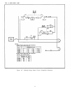
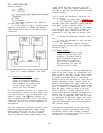
Figure 5-4.
Output Current, Test Setup
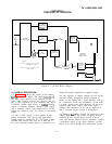
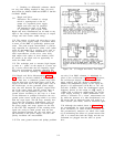
Load Regulation.
Definition: The change
∆Ε in the
static value of dc output voltage re-
sulting from a change in load resist-
ance from open circuit to a value
which yields maximum rated output
current (or vice versa).
To check the constant voltage load regula-
proceed as follows:
a.
Connect test setup as shown in Figure
OUT
b. Turn CURRENT controls fully clockwise.
c. Turn-on supply and adjust VOLTAGE con-
trols until front panel voltmeter indicates exactly
the maximum rated output voltage.
d. Read and record voltage indicated on dif-
ferential voltmeter.
e. Disconnect load resistors.
f.
Reading on differential voltmeter should
not vary from reading recorded in Step d by more
than 8mVdc for Models 6204B and 6205B or 10mVdc
for Model 6206B supply.
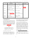
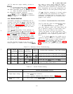
Figure 5-5.
Load Regulation, Test Setup
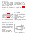
5-19 Line Regulation.
Definition: The change,
∆Ε in the
static value of dc output voltage re-
sulting from a change in ac input volt-
age over the specified range from low
line 10% less than nominal to high
line 10% more than nominal or from
high line to low line.
5-20 To test the constant voltage line regulation,
proceed as follows:
a. Connect variable auto transformer be-
tween input power source and power supply power
input.
b. Turn CURRENT controls fuIly clockwise.
c. Connect test setup shown in Figure 5-5.
d. Adjust variable auto transformer for low
line (104Vac).
e. Set METER switch to highest current
range and turn on supply.
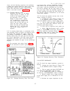
f. Adjust VOLTAGE controls until front
panel voltmeter indicates exactly the maximum
rated output voltage.
9.
Read and record voltage indicated on
differential voltmeter.
h. Adjust variable auto transformer for high
line (126Vac).
OUT
I
5-4