


TM 11-6625-2965-14&P
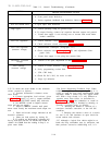
Table 5-3. Overall Troubleshooting (Continued)
SYMPTOM
CHECKS AND PROBABLE CAUSES
b. Front panel meter defective.
c. Series regulator feedback loop defective. Refer to Table 5-5.
Will not current limit
a. Q10 open. R81 defective.
High ripple a. Check operating setup for ground loops.
b. If output floating, connect lµf capacitor between output and ground.
c.
Ensure that supply is not crossing over to current limit mode under
loaded conditions.
Poor line regulation a.
Check reference circuit (Paragraph 5-55).
b. Check reference circuit adjustment (Paragraph 5-69).
Poor load regulation
a. Measurement technique. (Paragraph 5-17)
(constant voltage)
b. Check reference circuit (Paragraph 5-55) and adjustment (Para-
graph 5-69).
c.
Ensure that supply is not going into current limit.
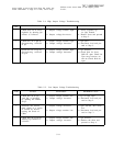
Oscillates (constant a.
Check C5 for open, adjustment of R30 (Paragraph 5-72).
voltage)
Poor stability
a.
Check ± 6.2Vdc reference voltages (Paragraph 5-55).
(constant voltage)
b. Noisy programming resistor R10.
c. CR1, CR2 leaky.
d. Check Rl, R12, R13, for noise or drift.
e. Stage Q1 defective.
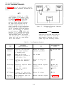
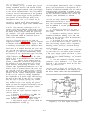
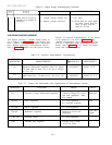
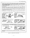
5-55 To check the zener diodes in the reference
circuit, proceed as follows:
a.
Connect differential voltmeter across
zener diode.
b. Connect appropriate load resistor, given
in Figure 5-4, across (+) and (-) output terminals.
c.
Turn VOLTAGE control fully clockwise.
d. Set METER switch to highest current
range and turn on supply.
e. Adjust CURRENT controls until panel
meter reads exactly the maximum rated output cur-
rent.
f.
Read and record voltage indicated on dif-
ferential voltmeter.
g.
Short out load resistor by closing S1.
h. If reading on differential voltmeter dif-
fers by more than 1.07mV for 6204B and 6205B or
.946mV for 6206B from the reading in Step f, re-
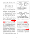
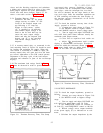
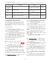
5-5b Series Regulating Feedback Loop. When
troubleshooting the series regulating loop, it is
useful to open the loop since measurements made
anywhere within a closed loop may appear abnor-
mal. With a loop closed, it is very difficult to
separate cause from effect. As described in
Tables 5-4 and 5-5, the conduction or cutoff ca-
pability of each stage is checked by shorting or
opening a previous stage, as follows:
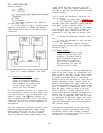
1.
Shorting the emitter to collector of a
transistor simulates saturation, or the full ON
condition.
2. Shorting the emitter to base of a transis-
tor cuts it off, and simulates an open circuit be-
tween emitter and collector.
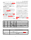
5-57 Although a logical first choice might be to
break the loop somewhere near its mid-point, and
then perform successive subdividing test, it is
place zener diode.
5-10