


TM 11-6625-2965-14&P
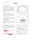
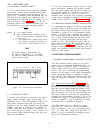
3-9 CHANGING CURRENT LIMIT
3-10 The current limit can be varied by adjusting
resistor R81, located on the printed wiring board.
This adjustment procedure is described in Para-
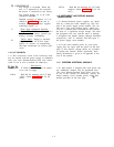
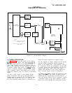
graph 5-74. In Models 6204B and 6206B, the cur-
rent limit may be reduced to a value lower than
that attainable by adjusting R81, by adding an ex-
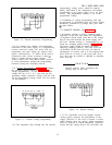
ternal resistor as shown in Figure 3-3. The ap-
proximate value of the external resistance (Rx) can
be determined by using the following equation
R
X
=1.75
I
where: I = the output current
E
R = the internal current sampling resist-
ance for the particular operating mode
to be used.
1.75 . the approximate voltage drop across
I
the internal sampling resistance at
the current limit crossover point.
NOTE
The power supply’s performance will
be somewhat degraded if it is operated
too close to (within 10OmA) the current
limit crossover point.
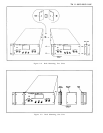
A1 A2 A6 A7 A8 A9 -S – GND + +S A10
Rx
R
L
Figure 3-3.
Current Limit Alteration
3-11 CONNECTING LOAD
3-12 Each load should be connected to the power
supply output terminals using separate pairs of
connecting wires.
This will minimize mutual cou-
pling effects between loads and will retain full
advantage of the low output impedance of the power
supply.
Each pair of connecting wires should be
as short as possible and twisted or shielded to re-
duce noise pickup. (If shield is used, connect one
end to power supply ground terminal and leave the
other end unconnected. )
3-13 If load considerations require that the output
power distribution terminals be remotely located
from the power supply, then the power supply out-
put terminals should be connected to the remote
distribution terminals via a pair of twisted or
shielded wires and each load separately connected
to the remote distribution termina1s. For this case,
remote sensing should be used (Paragraph 3-25).
3-14 OPERATION BEYOND NORMAL RATED OUTPUT
3-15 Although the supply can deliver greater than
the rated output on both the lower and higher volt-
age ranges without being damaged, it can not be
guaranteed to meet all of its performance specifi-
cations.
Generally when operating the supply in
this manner, the output is unstable when connect-
ed to a load.
When greater than the lower rated
voltage is required, the higher voltage range
should be used.
This range will deliver half as
much output current and all specifications will
apply as listed in Table 1-1. However, if the line
voltage is maintained above its nomina1 value, the
supply will probably operate within specifications
above its rated output.
3-16 OPTIONAL OPERATING MODES
3-17 REMOTE PROGRAMMING, CONSTANT VOLTAGE
3-18 The constant voltage output of the power
supply can be programmed (controlled) from a re-
mote location if required. Either a resistance or
voltage source can be used for the programming
device.
The wires connecting the programming
terminals of the supply to the remote programming
device should be twisted or shielded to reduce
noise pickup. The VOLTAGE controls on the front
panel are disabled according to the following pro-
cedures.
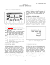
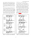
3-19 Resistance Programming (Figure 3-4). In
this mode, the output voltage will vary at a rate
determined by the programming coefficient (200
ohms per Volt for Model 6204B and 6205B or 300
ohms per Volt for Model 6206 B). The output volt-
age will increase by 1 Volt for each 200 ohms (or
300 ohms) added in series with the programming
terminals. The programming accuracy is 1% of the
programmed voltage. If greater programming ac-
curacy is required, it may be achieved by chang-
ing resistor R13 as outlined in Section V.
3-20 The output voltage of the power supply
should be zero Volts ± 20 millivolts when zero
ohms is connected across the programming termi-
nals. If a zero ohm voltage closer than this is re-
quired, it may be achieved by changing resistor
R6 or R8 as described in Section V.
3-2
E