


TM 11-6625-2965-l4&P
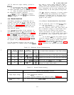
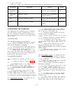
Table 5-7.
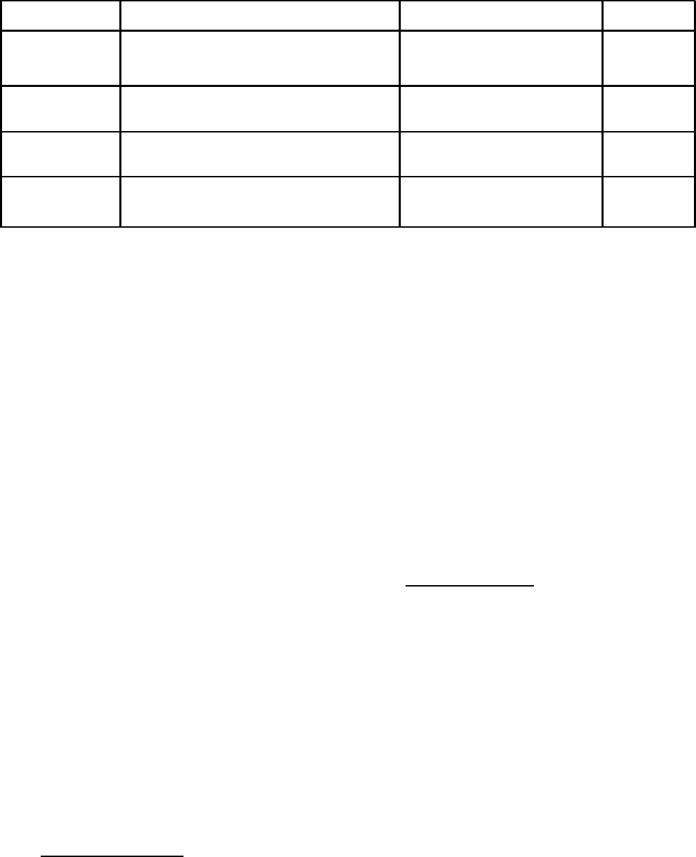
Checks and Adjustments After Replacement of Semiconductor Devices (Continued)
REFERENCE
FUNCTION CHECK
ADJUST
Q10, CR16 Current limit adjustment.
R81
(CR21)
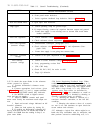
CR22 thru Rectifier diodes
Voltage across appropriate
CR29
filter capacitor.
VR1
Positive reference voltage
+6.2V line and load regu-
R46, VR1
lation.
VR2
Negative reference voltage
-6.2V line and load regu-
R46, VR2
lation.
5-60 ADJUSTMENT AND CALIBRATION
5-61 Adjustment and calibration may be required
after performance testing, troubleshooting, or re-
pair and replacement. Perform only those adjust-
ments that affect the operation of the faulty circuit
and no others.
5-62 METER ZERO
5-63 Proceed as follows to zero meter:
a. Turn off instrument (after it has reached
normal operating temperature) and allow 30 sec-
onds for all capacitors to discharge.
b.
Insert sharp pointed object (pen Point or
awl) into the small hole at top of round black plas-
tic disc located directly below meter face.
c.
Rotate plastic disc clockwise (
CW) until
meter reads zero, then rotate ccw slightly in order
to free adjustment screw from meter suspension, If
pointer moves, repeat Steps b and c.
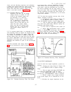
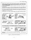
5-64 AMMETER TRACKING
5-65 To calibrate the ammeter, proceed as fol-
lows:
a. Connect test setup as shown on Figure
5-4.
b. Set RANGE switch to low voltage mode
and METER switch to lowest current range.
c.
Turn on supply and adjust VOLTAGE con-
trols so that differential voltmeter indicates ex-
actly 40Vdc.
d. Front panel meter should read 0.3 Amp
for Model 6204B and 6205B supplies, or 0.1 Amp
for Model 6206B supply. If it does not, adjust R72.
5-66 CONSTANT VOLTAGE PROGRAMMING CURRENT
5-67 Programming Accuracy. To calibrate the pro-
gramming current, proceed as follows:
a.
Connect an 8K, 0.1% resistor (18K re-
sistor for Model 6206B supplies) between termi-
nals -S and A6 on rear barrier strip.
b. Disconnect jumper between A7 and A8
(leaving A6 and A7 jumpered).
c.
Connect decade resistance box in place
of R13.
d. Connect differential voltmeter between
+S and -S terminals on rear barrier strip.
e.
Set RANGE switch to high voltage mode,
METER switch to high voltage range, and turn on
supply.
f. Adjust decade resistance box so that
differential voltmeter reads 40 ± 0.4Vdc for
Models 6204B and 6205B or 60 ± 0.6Vdc for Model
6206B supplies,
g.
Replace decade resistance with resistor
of appropriate value in R13 position.
5-68 Zero Output Voltage. To calibrate the zero
Volt programming accuracy, proceed as follows:
a.
Connect differential 1 voltmeter between
+S and -S terminals.
b. Short out voltage controls by connecting
jumper between terminals A6 and -S.
c.
Turn on supply and observe reading on
differential voltmeter.
d.
If it is more positive than O Volts, shunt
resistor R6 with a decade resistance box.
e.
Adjust decade resistance until differen-
tial voltmeter reads zero, then shunt R6 with re-
sistance value equal to that of the decade resist-
ante.
f.
If reading of Step c was more negative
than 0 Volts, shunt resistor R8 with the decade
resistance box.
g.
Adjust decade resistance until differen-
tial voltmeter reads zero then shunt R8 with a re-
sistance value equal to that of the decade box.
5-13