


i.
Reading on differential voltmeter should
not vary from reading recorded in Step g by more
than 8mVdc for Models 6204B and 6205B or 10mVdc
for Model 6206B.
5-21
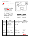
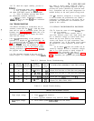
Ripple and Noise.
Definition: The residual ac voltage
which is superimposed on the dc
output of a regulated power supply.
Ripple and noise may be specified
and measured in terms of its RMS
or (preferably) peak-to-peak value.
Ripple and noise measurement can be made at any
input ac line voltage combined with any dc output
voltage and load current within rating.
5-22 The amount of ripple and noise that is pres-
ent on the power supply output is measured either
in terms of the RMS or (preferably) peak-to-peak
value. The peak-to-peak measurement is particu-
larly important for applications where noise spikes
could be detrimental to a sensitive load, such as
logic circuitry.
The RMS measurement is not an
ideal representation of the noise, since fairly
high output noise spikes of short duration could
be present in the ripple and not appreciably in-
crease the RMS value.
5-23 The technique used to measure high frequen-
cy noise or “ spikes”
on the output of a power sup-
ply is more critical than the low frequency ripple
and noise measurement technique; therefore the
former is discussed separately in Paragraph 5-31,
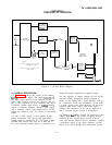
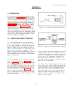
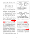
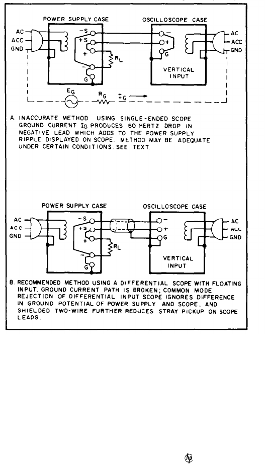
5-24 Ripple and Noise Measurements. Figure
5-6A shows an incorrect method of measuring p-p
ripple. Note that a continuous ground loop exists
from the third wire of the input power cord of the
supply to the third wire of the input power cord of
the oscilloscope via the grounded power supply
case, the wire between the negative output termi-
nal of the power supply and the vertical input of
the scope, and the grounded scope case. Any
ground current circulating in this loop as a result
of the difference in potential E
G
between the two
ground points causes an IR drop which is in series
with the scope input. This IR drop, normally hav-
ing a 60
HZ line frequency fundamental, plus any
pickup on the unshielded leads interconnecting
the power supply and scope, appears on the face
of the CRT. The magnitude of this resulting noise
signal can easily be much greater than the true
ripple developed between the plus and minus out-
put terminals of the power supply, and can com-
pletely invalidate the measurement.
5-25 The same ground current and pickup problems
Figure 5-6. CV Ripple and Noise, Test Setup
can exist if an RMS voltmeter is substituted in
place of the oscilloscope in Figure 5-6. However,
the oscilloscope display, unlike the true RMS
meter reading, tells the observer immediately
whether the fundamental period of the signal dis-
played is 8.3 milliseconds (1/120 Hz) or 16.7 mil-
liseconds (1/60Hz). Since the fundamental ripple
frequency present on the output of an supply is
120Hz (due to full-wave rectification), an oscillo-
scope display showing a 120Hz fundamental com-
ponent is indicative of a “clean” measurement set-
up, while the presence of a 60
HZ fundamental usu-
ally means that an improved setup will result in a
more accurate (and lower) value of measured ripple.
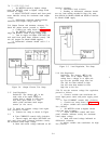
5-26 Although the method shown in Figure 5-6A is
not recommended for ripple measurements, it may
prove satisfactory in some instances provided cer-
tain precautionary measures are taken. One meth-
od of minimizing the effects of ground current flow
(IG) is to ensure that both the supply and the test
instrument are plugged into the same ac power
buss.
5-5
TM 11-6625-2965-14&P