


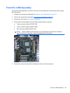
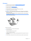

5. If using a new heat sink, remove the protective covering from the bottom of the heat sink and
place it in position atop the processor.
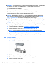
6. Secure the heat sink to the system board and system board tray with the 4 captive screws and
attach the heat sink control cable to the system board.
CAUTION: Heat sink retaining screws should be tightened in diagonally opposite pairs (as in
an X) to evenly seat the heat sink on the processor. This is especially important as the pins on
the socket are very fragile and any damage to them may require replacing the system board.
NOTE: After installing a new processor onto the system board, always update the system ROM to
ensure that the latest version of the BIOS is being used on the computer. The latest system BIOS can
be found on the Web at:
http://h18000.www1.hp.com/support/files.
Power Supply
WARNING! To reduce potential safety issues, only the power supply provided with the computer, a
replacement power supply provided by HP, or a power supply purchased as an accessory from HP
should be used with the computer.
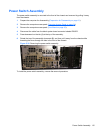
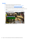
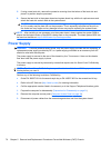
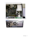
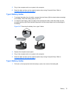
The power supply is secured to the rear of the chassis by four Torx screws. A lever on the chassis
floor also holds the power supply in place.
The power supply is secured by two security screws that require use of a Smart Cover FailSafe Key
to remove.
NOTE: The Smart Cover FailSafe Key is a specialized tool available from HP. Be prepared; order
this key before you need it.
Perform any of the following to obtain a FailSafe Key:
●
Order PN 166527-001 for the wrench-style key or PN 166527-002 for the screwdriver bit key.
●
Refer to the HP Web site (
http://www.hp.com) for ordering information.
● Call the appropriate number listed in the warranty or in the Support Telephone Numbers guide.
1. Prepare the computer for disassembly (
Preparation for Disassembly on page 31).
2. Remove the computer access panel (
Computer Access Panel on page 34).
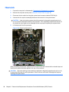
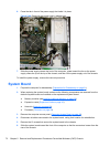
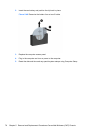
3. Disconnect all power cables from the mass storage devices and from the system board.
70 Chapter 5 Removal and Replacement Procedures Convertible Minitower (CMT) Chassis