


Index
Maintenance and Service Guide Index–4
spare part numbers 3–5, 4–54
product description
audio
1–4
chipset
1–1
Ethernet
1–4
external media card
1–5
graphics
1–2
hard drives
1–3
keyboard and pointing devices
1–6
memory
1–3
microphone
1–4
modem
1–4
operating system
1–6
optical drives
1–4
panels
1–2
ports
1–5
power requirements
1–6
processors
1–1
product name
1–1
security
1–6
serviceability
1–6
webcam
1–4
wireless
1–4
product name
1–1, 4–5
location
3–1
R
rear component 2–7
recovery methods
f11 recovery
8–4
recovery discs
8–4
Recovery Manager
8–4
recovery partition
8–4
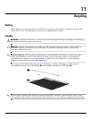
recycling
battery
11–1
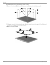
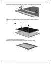
display
11–1
removal/replacement
preliminaries
4–1
procedures
4–5
restore points
8–3
restoring factory settings
5–2
right-side components
2–9
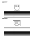
RJ-11 (modem) jack
3–4
location
2–9
pin assignments
9–4
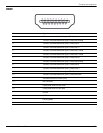
RJ-45 (network) jack
location
2–7
pin assignments
9–4
RTC battery
removing
4–19
spare part number
3–6, 4–19
Rubber Kit, spare part number
3–9, 4–6
S
scheduling backups 8–2
Screw Kit
contents
7–1
spare part number
3–9, 3–14
screw listing
7–1
security cable slot
2–9
Security menu
administrator password
5–3
Power-On password
5–3
security, product description
1–6
serial number
3–1, 4–5
service considerations
4–1
service tag
3–1, 4–5
serviceability, product description
1–6
Setup Utility
accessing
5–1
changing the language
5–1
Diagnostics menu
5–4
displaying system information
5–2
exiting
5–3
Main menu
5–3
navigating and selecting
5–2
restoring default settings
5–2
System Configuration menu
5–4
slots
ExpressCard
2–8
memory module
4–14
speakers
location
2–3
removing
4–26
spare part number
3–4, 4–26
specifications
AMD discrete graphics memory map
6–10
AMD UMA graphics memory map
6–11
Blu-ray ROM with LightScribe DVD±R/RW
SuperMulti DL Drive
6–4
display
6–2, 6–3
DVD±RW and CD-RW SuperMulti Double-Layer
Combo Drive
6–5
hard drive
6–3
I/O address
6–8
interrupts
6–6, 6–7
system DMA
6–5
system memory map
6–10, 6–11
stop button, location
2–4
subwoofer
location
2–10
removing
4–47
spare part number
3–5, 4–47
switch cover
removing
4–21