


Removal and replacement procedures
Maintenance and Service Guide 4–53
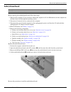
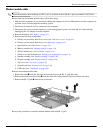
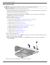
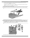
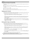
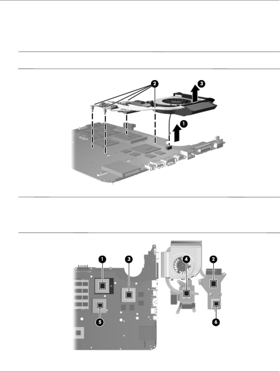
5. Turn the system board upside down, with the expansion port 3 and external monitor port toward you.
6. Disconnect the fan cable 1 from the system board.
7. Loosen the four Phillips PM2.5×6.0 captive screws 2 that secure the fan/heat sink assembly to the system
board.
8. Remove the fan/heat sink assembly 3 from the system board.
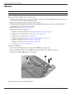
✎
Due to the adhesive quality of the thermal material located between the fan/heat sink assembly and system board
components, it may be necessary to move the fan/heat sink assembly from side to side to detach the assembly.
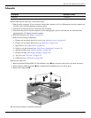
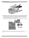
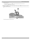
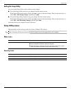
✎
The thermal material must be thoroughly cleaned from the surfaces of the fan/heat sink assembly and the system
board each time the fan/heat sink assembly is removed. Thermal paste is used on the processor 1 and the heat
sink section 2 that services it. Thermal pads are used on the graphics subsystem chip 3 and graphics/heat sink
contact 4, the Northbridge chip 5 and Northbridge contact 6. Replacement thermal material is included with all
fan/heat sink assembly, system board, and processor spare part kits.
Reverse this procedure to install the fan/heat sink assembly.