


15
Installation
Quick Installation Outline
The following is a quick preview of the steps required for first time installations. Each item is discussed in
detail later in this section.
Determine clearance, ventilation and service access requirements.
Determine checkout counter layout taking into account package flow, cable routing, and power
requirements.
Choose the mounting option which provides the best cable/power access and unit stability.
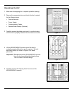
Unpack the unit.
Make the appropriate countertop cutouts and install all support brackets.
Place the unit in the counter.
Install the platter.
Follow the steps under the correct interface to connect the cables and power supply.
Configure the unit for the correct interface.
Calibrate the Diva scale.
Site Requirements
Before installing your MS2420/MS2430 scanner/Diva scale, please consider the following items.
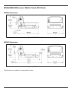
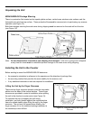
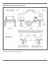
Vertical Clearance
A minimum clearance height of 5.25" from the checkout counter surface is needed for the vertical 'hood' on all
of the scanner models.
Ventilation and Spacing
All MS2420 and MS2430 models have a die-cast housing to dissipate heat allowing the unit to operate without
a ventilation fan. The temperature surrounding the unit is recommended not to exceed 40°C (104°F). There
should be adequate convection and minimal heat producing equipment in close proximity of the unit.
A cooling fan with a filter is recommended if there will be a conveyor motor or other heat producing equipment
close to the unit that will create a high temperature environment.
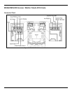
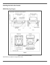
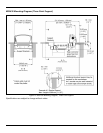
Adequate spacing between the unit and the checkout counter opening is required for proper operation of the
scale. When the scanner/Diva scale model is mounted properly, the scale platter should be able to move up
and down freely without hitting the edges of the checkout counter cutout. Refer to Installing the Unit in the
Counter beginning on page 18 of this guide for detailed cutout dimensions and mounting instructions.