


Notes:
1. The enumeration of the Ethernet controllers in a blade server is
operating-system dependent. You can verify the Ethernet controller designations
a blade server uses through your operating system settings.
2. The routing of an Ethernet controller to a particular I/O-module bay depends on
the type of blade server. You can verify which Ethernet controller is routed to
which I/O-module bay by using the following test:
a. Install only one Ethernet switch module or pass-thru module, in I/O-module
bay 1.
b. Make sure the ports on the switch module or pass-thru module are enabled
(I/O Module Tasks → Management → Advanced Management in the
management module Web-based user interface).
c. Enable only one of the Ethernet controllers on the blade server. Note the
designation the blade server operating system has for the controller.
d. Ping an external computer on the network connected to the switch module
or pass-thru module.
If you can ping the external computer, the Ethernet controller you enabled is
associated with the I/O module in I/O-module bay 1. The other Ethernet
controller in the blade server is associated with the I/O module in I/O-module
bay 2.
3. If you have installed an I/O expansion option on a blade server, communications
from the option are routed to I/O-module bays 3 and 4. You can verify which
controller on the option is routed to which I/O-module bay by performing the test
in note 2, using a controller on the I/O expansion option and a compatible
switch module or pass-thru module in I/O bay 3 or 4.
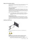
Power modules
Your BladeCenter unit comes with one pair of 220-volt hot-swap power modules in
power bays 1 and 2 that provides power to all the BladeCenter modules and to
blade bays 1 through 6. The BladeCenter unit supports a second pair of power
modules in power bays 3 and 4 that provides power to blade bays 7 through 14.
The following table summarizes the application for each power module.
Bays Power module function
1 and 2 Provides power to all the BladeCenter modules and to blade bays 1 through 6
3 and 4 Provides power to blade bays 7 through 14
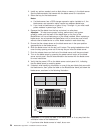
Power modules are not needed in bays 3 and 4 until you begin installing blade
servers and options in blade bays 7 through 14.
Note: If you install a blade server that has a storage expansion unit option
attached in blade bay 6, the option will use blade bay 7; power modules will
be required in power bays 1, 2, 3 and 4.
Each active power module supplies 12 volts of power to the blade bays it services.
Important: Plug one end of each power-module power cord into the power module;
plug the other end of the power cord into a 220-volt power distribution unit (PDU).
Chapter 2. Installing options 17