


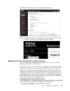
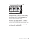
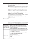
MAC MAC MAC
1a 2a 3a
1b 2b 3b
Switch A
Mgmt
Mod
Switch B
1 Gbps links
1 Gbps or
100 Mbps links
1 Gbps links
10/100 Mbps
100 Mbps
links
Note: 2nd switch module is optional
12
3
4
56
7
8910
11 12
13
14
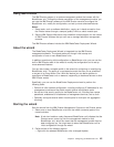
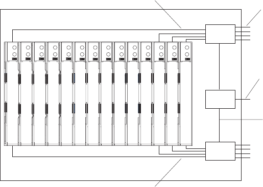
Each blade server has two independent Ethernet controllers, each with its own
MAC address and a dedicated 1000-Mbps link to one of the switch modules in I/O
module bays 1 and 2 (Controller 1 to Switch A and Controller 2 to Switch B in this
diagram). In this configuration (the default), the blade servers share access to four
external ports on each switch. There is no internal data path between the two
switches within the BladeCenter chassis; an external network device is required for
data packets to flow from one internal switch to the other.
The management module has a separate internal 100-Mbps link to each switch.
These links are for internal management and control only. No data packets are
allowed to flow from application programs on the blade servers to the management
module over this path. A separate, nonswitched path (not shown) is used for
communication between the management module and a service processor on each
blade server.
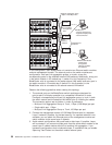
A typical, preferred BladeCenter network topology is shown in the following
illustration. See the IBM Eserver BladeCenter Planning and Installation Guide for
more information and other topologies and guidelines.
Chapter 4. Configuring your BladeCenter unit 49