


To replace an input power distribution assembly, see “Replacing an input power distribution assembly in
a 5802 or 5877 expansion unit with the power turned off.”
Related information
Before you begin
Identifying a failing part
Stopping the system or logical partition
Replacing an input power distribution assembly in a 5802 or 5877
expansion unit with the power turned off
Learn how to replace an input power distribution assembly in a 5802 or 5877 expansion unit if you
removed a failing assembly and must replace it.
If your system is managed by the Hardware Management Console (HMC), use the HMC to replace an
input power distribution assembly. For instructions, see Exchanging a part by using the Hardware
Management Console.
If your system is managed by the IBM Systems Director Management Console (SDMC), use the SDMC to
complete the steps for replacing a power supply in the server. For instructions, see Replacing a part by
using the Systems Director Management Console.
To replace an input power distribution assembly in an expansion unit for a system that is not managed
by the HMC or SDMC, complete the following steps:
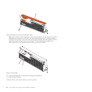
1. If you are replacing an input power distribution assembly because of a failure, remove the failing
part, as described in “Removing an input power distribution assembly from a 5802 or 5877
expansion unit with the power turned off” on page 25.
2. Perform the prerequisite tasks, as described in Before you begin.
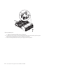
3. Open the rear rack door.
4. Attach the wrist strap.
Attention:
v Attach a wrist strap to an unpainted surface of your hardware to prevent electrostatic discharge
(ESD) from damaging your hardware.
v When using a wrist strap, follow all electrical safety procedures. A wrist strap is for static control.
It does not increase or decrease your risk of receiving electric shock when using or working on
electrical equipment.
v If you do not have a wrist strap, just prior to removing the product from ESD packaging and
installing or replacing hardware, touch an unpainted surface of the system for a minimum of 5
seconds.
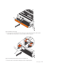
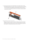
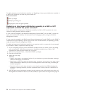
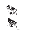
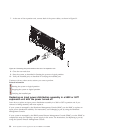
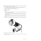
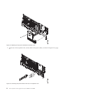
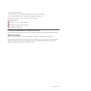
5. Push the input power distribution assembly into the expansion unit until it latches into place, and
then tighten the thumbscrew (A) to secure the assembly in place as shown in Figure 30 on page 29.
28 Power Systems: Power supplies for the 9117-MMB or 9179-MHB