


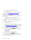
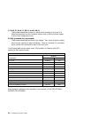
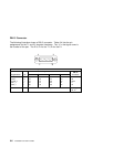
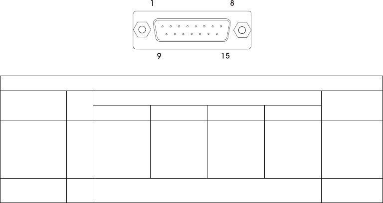
DB-15 Connector
The following illustration shows a DB-15 connector. Table 6-4 lists the pin
assignments for the T1 and E1 electrical interfaces. The “x” in the signal name is
the number of the port. The ID is 7h for the T1; 2h for the E1.
Table 6-4. DB-15 Connector Pin Assignments
Signal Name I/O
36-pin Connector
DB-15
Connector0 1 2 3
TX1_x O 33 29 23 19 01
TX2_x O 34 30 24 20 09
FGND_x --- 16 12 08 04 02,04
RX1_x I 35 31 25 21 11
RX2_x I 36 32 26 22 03
FGND --- Housing Housing,
08, 15
6-6 Installation and User's Guide