


http://www.national.com
2
Hardware
1. CLC3790093 Data Capture Board
(CLC-CAPT-PCASM)
2. CLC Evaluation Board. Several ADC products can
be evaluated with this system. Currently, the choices
are the CLC5956 (12-bit 65MSPS ADC), or the
CLC5958 (14-bit 52MSPS ADC). Each product
has a unique evaluation board (CLC5956PCASM
or CLC5958PCASM) which plugs into the data
capture board.
3. Personal Computer. An IBM-Compatible PC running
Windows
®
95, Windows
®
98, or Windows
®
NT. The
PC should have an available serial port capable of
operating at 115,200 baud. These ports are usually
labeled and referred to as COM1 and COM2. The
captured data is stored in a file on the PC to allow
custom analysis.
4. Serial Cable. A standard serial interface cable is
provided. This cable connects the data capture
board to the PC.
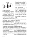
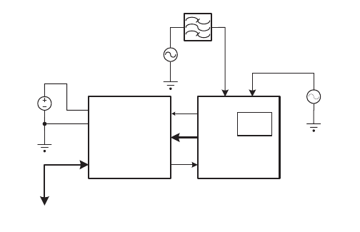
5. Power Supply. The data capture board requires a
single +5V supply. This power is applied at
connector J3. A 2-amp supply will provide enough
current for the evaluation board and the data cap-
ture board. Note that the power for the evaluation
board is provided from the data capture board
through the 64-pin connector J1.
6. Input signal. You can provide any type of input
signal that you feel is appropriate to your system
testing. The data analysis software provided with the
data capture board is oriented toward analysis of
single tone sinewave inputs. Our recommendation
for high purity, low phase noise reference signal
sources is the Hewlett Packard HP8644B synthe-
sizer. It provides an excellent input stimulus for
evaluating ADC performance.
7. Bandpass or lowpass filter. Even with a good
sinewave source, you will need to filter out the har-
monics of the signal source. A bandpass filter also
enables filtering of the wideband noise of the refer-
ence source. As an example, Allen Avionics
(Mineola, NY) passive filters are used for most of
our converter testing.
8. Clock Source. If you wish to test the ADC with a fixed
clock frequency, you may install a standard TTL
oscillator in the socket provided on the evaluation
board. Otherwise, you will need to provide a low
phase noise sinewave or square wave clock source
at the appropriate SMA connector on the evaluation
board. An amplitude of 10 to 16dBm is recommended.
Here, again, the HP 8644B is a good choice.
Software
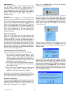
1. National Semiconductor Software. All of the
required software is provided on a CD-ROM. To
install the software now, insert the CD-ROM into
your computer and follow the directions. The default
installation copies all of the files to a directory called
“c:\nsc”. The data capture software is called
“capture.exe”.
2. Matlab. A copy of Matlab version 5.1 or later is
required to operate the analysis routines. If you sim-
ply wish to capture data to a file on your PC and pro-
cess the data with your own analysis software, then
you will not need Matlab. For more information
about Matlab, please see their website at http://
www.mathworks.com.
3. Matlab script files. The Matlab script files for data
analysis are located in the “c:\nsc\mfiles” directory.
These script files are run from the Matlab command
prompt.
Documentation
The CD-ROM includes all of the following documentation,
with the most current versions available on our website at
http:// www.national.com:
1. CLC5956 data sheet
2. CLC5958 data sheet
3. Data Capture Board User’s guide (this document).
Additional information is included on other products and
their evaluation boards. If you are evaluating the
Diversity Receiver Chip Set, please refer to Section III of
this manual.
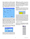
Operation of Data Capture Board
When evaluating the performance of an ADC, the data
capture board has two main modes of operation. In the
first mode, data is captured from the evaluation board
under test at the full sample rate of the ADC. A contigu-
ous set of 32k data samples is captured into a FIFO
memory on the board, and then this data is moved over
to the PC at a slower rate. The data set is stored in a file
on the hard drive for later analysis. The data is stored in
an ASCII file in exactly the format that it is output from the
converter. For the CLC5956, the two’s complement 12-Bit
data is stored as numbers ranging from 0 to 4095. In the
case of the 14-bit ADC5958, the two’s complement data
ranges from 0 to 16383. Each value is terminated with a
carriage return, hexadecimal 0D. Note that the two’s
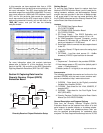
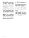
BPF
Ain
CLK
VCC
GND
OPTIONAL
CLOCK SOURCE
FILTERED
SIGNAL
SOURCE
+5V
VCC
(2A)
Data
10-16dBm
To PC Serial
COMM PORT #1 or #2
64P I/O
CONNECTOR
Clock
Power
Optional
TTL
Oscillator
ADC
Evaluation
Board
Data
Capture
Board
Serial I/O