


9 http://www.national.com
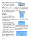
The
“Configure I/O”
button opens the user port option
menu window. Clicking the left mouse button selects the
desired port (the default Windows address and IRQ is
assumed). Clicking the
“OK”
button sends an identifica-
tion command out the selected port and listens for the
Capture board to echo back the command. This function
requires that DC power and data clock is present. If the
hardware is functional and the proper PC port connected,
the Configure I/O window will then close and return back
to the user Control Panel. Capture Board LED#6 will be lit
if the data clock is present.
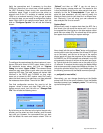
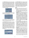
If the incorrect serial port is selected or if the hardware is
dysfunctional (i.e. missing power or clock) the program
will return an error-warning window.
Click the
“OK”
button to clear the warning and then try
the other PC serial port in the
“I/O Configuration”
window or correct the hardware problem.
The
“Change Data File”
button enables a dialog window
where the user can direct the location of the captured
data file. The desired file name and path can be typed
into the box. Clicking the left mouse on the button on the
right side of the file name box opens a standard browser
window to search for an appropriate file name. The
“Default”
button restores the default directory and file
name. The attached Matlab script analysis routines (*.m
files) assume that the data is located at this location;
however, the user can edit the routines to load from the
appropriate location. Clicking the
“OK”
button updates
the Capture program’s *.ini file and returns to the Capture
Control Panel.
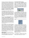
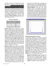
The
“Configure Capture”
button invokes the user dialog
window for the remainder of the configuration options.
After selecting the desired options, a left mouse click on
“OK”
stores the configuration variables and returns to
the Control Panel. Positioning the mouse pointer over the
Progress Bar inside the Control Panel pops up a text bub-
ble which displays the configuration variables used when
the Capture Program is started. Next is a discussion of
the Mode functions and the related sub-functions:
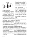
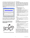
MODES
There are four primary modes in which to run the data
capture system, each with its own associated options:
1.
Capture
mode configures the Capture Board for
data reception from the DRCS evaluation board.
Both serial and the parallel output ports can be used
as the source data path.
a) The
24-Bits
option captures serial DRCS data
FROM
either of the two serial data ports. The
Capture 1st
Bit option should be selected for this
mode of data capture. With CLC5902 DDC in
“packed”
and
“mux_mode”
, the
AOUT
data
source contains both phases of both DDC channels.
The two
Channel
buttons select the desired DDC
channel to be stored in the SRAM. The four
Phase
buttons select either I or Q phase or the ordering of
alternating I/Q phases. In this latter case, the 32K
RAM space is shared. Therefore, only 16K points of
each phase are collected. If the
BOUT
data source
is selected, the CLC5902 DDC must be instructed
accordingly (i.e. “packed” and “mux_mode” off). With
the DDC in its default output format, the
BOUT
serial port is disabled.
b) The
Upper 16-Bits
and
Lower 16-Bits
options
enable the CLC5902 DDC’s parallel outputs. In this
configuration the DDC parallel output mux is
controlled by the FPGA through the 64 pin Euro
connector (be sure that the DRCS board SW1
“POUT”
switches are OFF/OPEN). The user
selects
Channel
and
Phase
and the FPGA instructs
the DDC which channel, phase, and which half of
the 32-bit output word to send out its parallel data
bus. This configuration uses the FIFO for temporary
data storage.
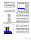
2.
Histogram
mode returns the Capture Board to the
24-bit serial data mode. As before, with the
CLC5902 DDC in “packed” and “mux_mode”, the
AOUT
data source contains both phases of both
DDC channels. A DDC change is required to enable
the
BOUT
. The
Capture 1st Bit
option should be
selected as before. In the
Histogram
configuration,
the program
Start
button first sets every SRAM
location value to zero. The hardware then samples
the data, reads the value at that memory location,
increments the value, and writes back the updated
value. The process continues until one of the
memory values reach the target value set by SW1